Facebook
 Google
 GitHub
 Linkedin
Using a Serial LCD with a PICAXE
Using an LCD increases the versatility of any microcontroller by displaying data outputs and memory contents. This serial adapter uses only one I/O.
Project Overview
This project describes in detail how to assemble and connect a serial backpack adapter to a liquid crystal display (LCD) and to a PICAXE microcontroller, as well as how to program the PICAXE to drive the LCD. All instructions and descriptions in this article are based on the assumption that you are using the SMDLCD117 2400 baud kit and a 20x4 LCD, both available from Modern Device.
While this project deals specifically with a PICAXE 08M2 µC, much of the information provided will apply to adding an LCD117 to a PIC, Arduino, Raspberry PI, or most other microcontrollers.
A Serial LCD...What's That?
A discussion of serial adapters for liquid crystal displays is available in the article entitled, "An LCD for Your Microcontroller Using a Single I/O." If you haven't already read it, you should do so before continuing with this project.
Modern Device SMDLCD117
The Modern Device surface mount LCD117 kit is shown below. It includes the PCB, a 1x16 pin female header, a 2x8 pin female header, a right angle 3-pin male header, a straight 3-pin male header, a 12-inch three-conductor cable, and a straight 16-pin male header.

The SMD parts are already soldered in place. All that's left to solder is the female header, which is placed on the back side of the PCB, and the right angle 3-pin male header which goes on the front side of the PCB. The straight 16-pin male header is to be placed on the back side of the LCD (shown below) and soldered.

Assembly and Connection of the LCD117 to the LCD PCB
The LCD117 serial adapter is designed to connect to the rear of the LCD PCB as shown in the photo below.

Refer to the photo and assemble the serial adapter to the LCD as follows.
1. Place the 16-pin male header on the back side (opposite the display) of the LCD PCB. Solder one pin and check to see if the header is perpendicular to the PCB; if not, heat the joint and straighten the header. Solder the remaining pins.
2. Place the 16-pin female header on the back side (opposite the SMD components) of the serial adapter PCB. Solder one pin and check to see if the header is perpendicular to the PCB; if not, heat the joint and straighten the header. Solder the remaining pins.
3. Place the right angle 3-pin male header on the front side (with the SMD components) of the serial adapter PCB. Solder one pin and check to see if the header is straight on the PCB; if not, heat the joint and straighten the header. Solder the remaining pins.
4. Fit the serial adapter PCB 16-pin female header onto the 16-pin male header on the LCD PCB. Insert the male pins fully into the female header.
5. Fit one end of the 12-inch three-conductor cable onto the right angle 3-pin male header on the serial adapter PCB. Ensure that the black wire is connected to the bottom pin (Gnd,) the red wire is connecte to the middle pin (+5V,) and the white wire is connected to the top pin (Rx.) Insert the male pins fully into the female connector on the cable.
Connecting to the PICAXE
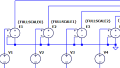
Construct a PICAXE circuit to drive the serial LCD; a suitable circuit is shown in the schematic diagram below

Here is a photo of the PICAXE 08M2 serial LCD driver circuit built on a solderless breadboard. Connect the LCD cable to the breadboard as shown, but don't connect power to the breadboard yet.

Recheck all the connections, especially on both ends of the LCD cable. Once you are certain all the connections are correct, apply +5V (and ground) to the solderless breadboard as shown in the photo above.
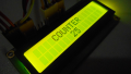
If all is well, the LCD should light up, and show a boot screen for a few seconds. The boot screen should look like the picture below, but the colors may be different, depending on your LCD.

After about four seconds, the boot screen should disappear, but the LCD should remain lit and a cursor should be blinking in the top left corner. If so, all is well! If the display shows no signs of life, disconnect the power, and recheck all the connections.
If the display comes to life, but no characters appear, try adjusting the contrast with the potentiometer (pot) on the LCD117 PCB. It is marked as "R2" and requires a very small screwdriver and a deft touch to adjust. Gently rotate the adjusting screw while watching the display; too far one way and the characters will be too dim to see, and too far the other way and all of the pixels in all the character blocks will be fully visible. Once set, the pot should require no further adjustments unless you move the LCD117 to a different display.
LCD Commands
The operational sequence to control what is displayed on the LCD is a two-step process. The program code running on the PICAXE contains LCD commands that are sent to the serial adapter; the LCD117 firmware converts the serial LCD commands to HD44780 parallel control signals. That latter step is completely under the control of the LCD117, but the first step is entirely dependent upon the PICAXE code for the LCD commands, which must strictly adhere to the format originated by Peter Anderson. Those commands and their format are described in this summary. As you see, every command must begin with a ? (question mark) and all commands are case sensitive. If the command specifies a capital letter, use one, but if a lower case letter is defined, don't use a capital letter.
Control Commands
There are four "Control Commands" which are not normally used in regular programs, but instead are used to set up the LCD117 to accommodate the LCD being used, and some user preferences. The control commands are explained in the table below.
| LCD117 Control Commands | ||||
|---|---|---|---|---|
| Parameter | Format | Explanation | Example | Default |
| LCD Geometry | ?Gyxx |
y = number of rows (2 or 4), x = number of characters (16, 20, 24, or 40) |
?G416 = 4 rows x 16 characters | 4x20 |
| Tab Size | ?sx | x = number of spaces per tab (1 - 8) | ?s6 = 6 spaces per tab | 4 |
| Backlight Intensity | ?Bxx |
xx = hexadecimal number from 00 through ff (256 possibilties) |
?B40 = 64 | 128 |
| Cursor Style | ?cx |
x = 0 (no underline & no blinking block,) 1 (no underline & blinking block,) 2 (underline & no blinking block,) or 3 (underline & blinking block) |
?c2 = underline & no blinking block | 3 |
Note that the right-most column in the table shows the default settings that are in the LCD117 firmware when it ships from Modern Device. Look at the boot screen picture above, and compare the boot screen display to defaults in the Control Command table. You should probably not change the default settings until you gain some experience using the LCD117.
- The "117G" in the top left corner is the revision number of the firmware in the LCD117 adapter.
- The "2400" indicates the baud rate at which the device operates; other possiblities are 4800, 9600, and 19,200 baud. (Some PICAXE microcontrollers can operate at baud rates other than 2400, but 2400 is standard and is recommended.) The baud rate is hard coded in the LCD117 firmware, and cannot be readily changed by the end-user.
- The "4x20" indicates a four line by 20 character display; other choices are 2X16, 2X20, 2X24, 2X40, and 4X16.
- The "4" in the second line indicates that the length of a tab is set to four spaces; valid settings are from 1 through 8 spaces.
- The eight blocks of increasing height in the center of the second line are user defined characters, and can be changed.
- The "40" in the second line indicates that the LCD backlight is set to a hex value of 40; valid settings are from 00 through 80, thus 40 is at mid-range.
Writing PICAXE BASIC Code for the LCD117
PICAXE code to drive the LCD117 is not complex, but it must be written to adhere to PICAXE BASIC requirements and use the commands in the LCD117 summary.
The code sample below is just that...a sample. It doesn't really do anything except send some characters to the LCD117, which translates them to the HD44780 format for the LCD to use. Note that every string sent begins with a serout command followed by the identification of the PICAXE 08M2 pin to use, followed by "T2400" to instruct the 08M2 to transmit the data to the LCD117 true (i.e., not inverted) at 2400 baud. The opening and closing parentheses contain all the data and text to be sent in the string. The open and closing quotation marks are required by the firmware in the LCD117, and the question mark indicates that a command follows. All those elements must be included in order for the LCD to display the characters desired.

Download the code and try it. Watch the results and compare what you see to the code instructions. Then, refer to the command summary, make some changes, and see if the LCD shows what you planned. There's nothing any better than learning by doing.
Final Words...
The LCD117 is a very versatile serial to parallel adapter and, paired with a 20x4 LCD, will be a great asset to your PICAXE projects. The firmware also contains some enhanced features such as a Big Number mode, and the ability for you to create custom characters to display. Try them out for yourself, and watch for more PICAXE projects coming up soon on AAC.
Give this project a try for yourself! Get the BOM.