 Facebook
 Google
 GitHub
 Linkedin
How to Keep a Power Transistor Cool Using a Heat Sink
Handling heat in electronics. Which components create heat, which components suffer from heat. Basics of heatsinking.
Recommended Level
Beginner
Which devices generate heat?
With regard to circuits, the broad answer to this question is – all of them. Heat in circuitry is caused by resistance, a property found in every part of a circuit: wire, capacitors, resistors, semiconductors, batteries, solder. Heat is the effect caused by current traveling through a resistance in which power is lost to the surrounding media in the form of a temperature increase. In many of these components the heating is trivial; unless you are a power engineer, you probably will not have to deal with keeping copper wire cooled with mineral oil. However for some of these devices heat is a real issue that needs to be addressed-- in particular the heat generated by semiconductors.
Analog
In analog applications of semiconductors, heat will most often be encountered in voltage regulators and output transistors. With regulators, the power lost to heat is pretty easy to conceptualize: if you have a 12 Volt supply and wish do generate an output of 5 Volts using a regulator, then with a circuit drawing one Amp of output current, the regulator has 12 Watts going into the device, and 5 Watts coming out. What happened to the other 7 watts? They have been burned off in the form of heat; we will come back to this example when talking about dissipating this heat.
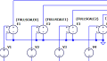
On to output transistors- in an ideal world, transistors do not dissipate power when they are fully on or fully off. To illustrate this we can use the classic example of an ideal switch:
.png)
Case 1: Switch Open
.png)
Case 2: Switch Closed
In case 1, the switch is an open circuit and no current may flow through the switch or the resistor because we have from Ohm’s law that:
Now in case 2, the switch has been closed and now there is 1mA of current flowing through the switch and resistor. Now that there is current through our switch, let’s look at how much power it is dissipating. We know that an ideal closed switch is a perfect conductor, i.e. presenting no resistance; so our equation for power dissipated by the switch becomes
Thus, no power is dissipated by the switch in either the closed or open cases. However in real life we are not using ideal components: BJT’s have a VCE_Sat usually around 0.2 Volts when fully on and even MOSFETs have a small resistance RDS_On when fully on. For most cases these values are low enough that the power dissipated is very low; it is the state between off and on that dissipates the most power. In a power handling device such as an audio power amplifier, transistors will amplify sinusoidal waveforms to be delivered into a low impedance load, usually a speaker.
A properly biased Class – A output (one that is operating for the entire 360 degree wave cycle) will have this output transistor constantly transitioning between off and on, never quite reaching either, in a sinusoidal pattern mimicking that of the input. Thus a Class – A amp will dissipate the most power with zero signal applied, because at this point the transistor will be exactly halfway between the off and on states. This is important to note, because the power dissipated during the zero input condition is what will be used to determine the size of heatsink needed to keep the transistors from overheating. A Class – B output (in which each output device operates for exactly half of the wave cycle) will generate much less heat, as it spends half its time in the fully off state to which it is biased. In this case the amplifier dissipates the least amount of power as heat in the zero input signal condition, making Class – B amplifiers more thermally efficient than Class – A.
Digital
In digital applications of semiconductors, the goal is to switch between on and off states at the clock frequency, spending no time in between and thus dissipating no power. Once again we run into the issue that these devices are not perfect; for a given CMOS transistor there is a minimum transition time based on the dimensions and parasitic capacitances of the physical device which limits how fast it can switch between off and on. During this transition time, the device will be dissipating power in the form of heat. When the clock speed of a digital chip is increased, the time spent in either off or on states decreases but the transition time remains the same. Thus as the speed increases, the ratio of steady-state to transition-state decreases and more power is lost to heat. This is one of the primary reasons that over-clocking a computer’s CPU usually requires greater measures to be taken to cool the chip.
Beating the Heat
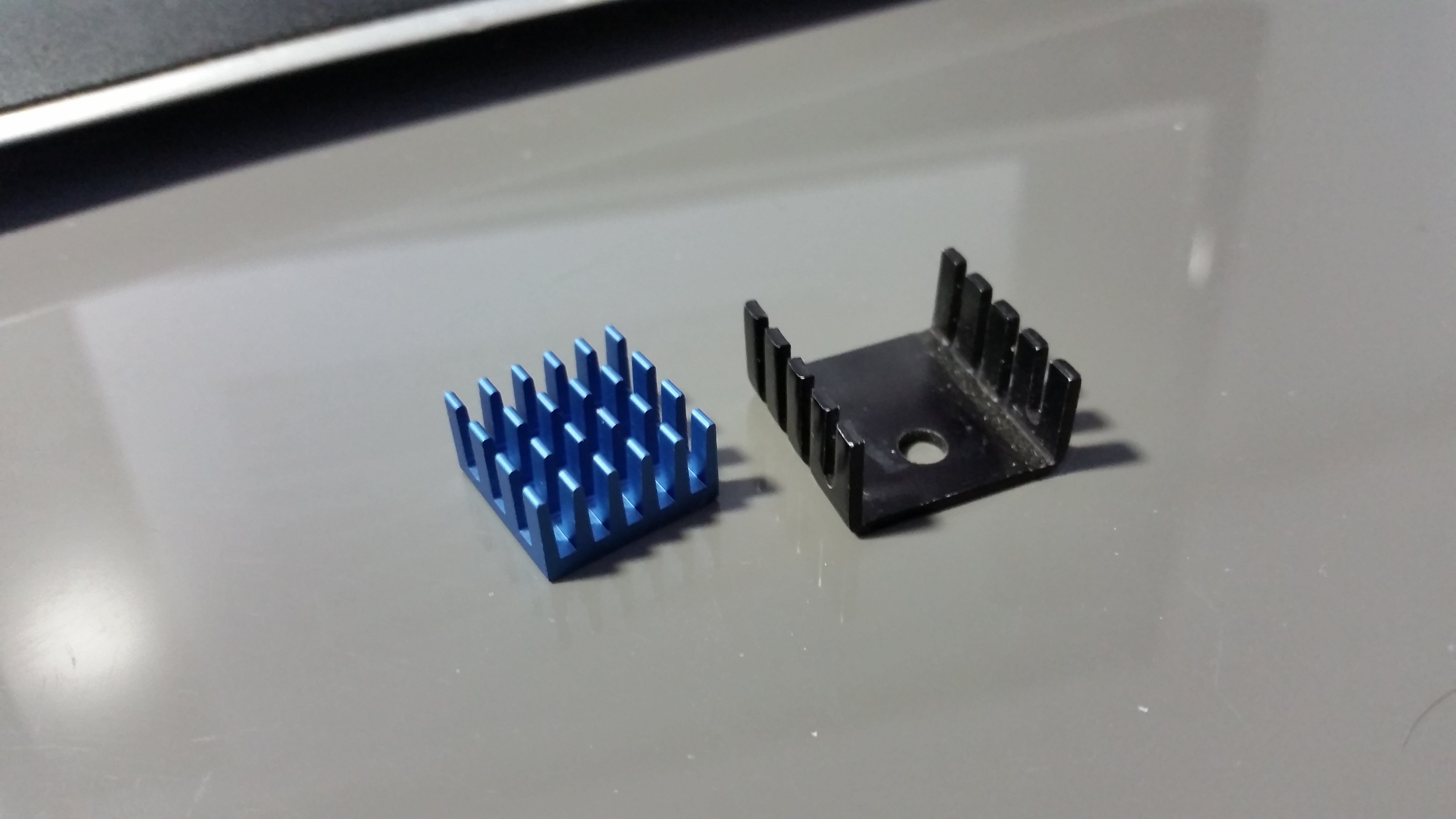
Now we know how and why devices dissipate heat, so how do we control it? Just as there are good conductors of electricity, there are good conductors of heat. Materials such as copper and aluminum are excellent conductors of heat and are used as devices called heatsinks to help move heat from a semiconductor to the air quickly, preventing thermal damage to the chip. The more surface area a heatsink has, the faster it can transfer heat to the air. The picture below depicts a pair of heatsinks; the fins on the heatsinks are what increase the surface area.
The comparison of electrical conductors to heat conductors is no accident, and the equations governing both are analogous: Ohm’s Law --> Voltage = Resistance * Current Temperature Rise --> delta Temperature = Thermal Resistance * Power Dissipation or, using the standard variable designations:
For example, the voltage regulator from earlier was giving us 5 Volts from a 12 Volt supply at 1 Amp, dissipating 7 Watts in so doing. A LM7805 would be a typical device that would accomplish this, but what kind of heatsink do we need to help the regulator dissipate that 7 Watts? Checking the datasheet for the LM7805 (available via a quick Google search) we see that the thermal resistance from the semiconductor junction to the external case of the device is 5 degrees Celsius per Watt, and the resistance from junction to ambient air is 65 degrees Celsius per Watt.

Using our temperature equation and the specifications from the datasheet we see that:
Thus the MINIMUM thermal resistance we need in a heatsink will be 9.29 C/W; however in engineering we always want to give ourselves a margin of error, in this case lets go with 20%. This means we actually need to find a heatsink with a thermal resistance of not more than 7.43 C/W. At this point we can go to an electronics part distributor website such as Mouser or Digikey and search for heatsink that will fit a TO-220 case and have the right thermal resistance. I quickly found part No. 532-504222B00 from Mouser which has a thermal resistance of 6.4 C/W; this will work perfectly for our application. When attaching the heatsink it is important to use thermal compound between the case and heatsink. This is because it will fill up any tiny pockets of air that may be between the two and cause an increase in thermal resistance- we definitely don't want that.
Heat is something any engineer, regardless of discipline, will encounter in their career. It is important to recognize the limitations of your hardware and be able to compensate using the appropriate heatsink. Datasheets will always be your friend as you crunch numbers to try and discern what the best course of cooling will be in your particular situation, and remembering to give yourself a margin of error will set you up for success.


This is good info, especially the switch example. Thanks!
What is Adiabatic Cooling System ?
Adiabatic cooling system is the process of reducing heat energy with the help of conventional natural methods like sprinkling of water to maintain the temperature. It is very traditional methodology initially used by Roman, Australian, Chinese and Persian Societies. The concept comes into picture from the evaporative air conditioning systems at homes where water is added to a pad or rooftop through which air is pinched into reduce the temperature. Because of which we will obtain lower temperature at the input which will reduce the energy costs converting the air to the required temperature. This principle is known as “Adiabatic cooling” process.
For more:http://www.maniks.com/manufacturer/adiabatic-cooling-system-2/
Reading the graph in the datasheet the 6.4 C/W rating pertains to forced convection. For natural convection the temperature rise is 60C at 7 Watts or a thermal resistance of about 8.6 deg C/W.