 Facebook
 Google
 GitHub
 Linkedin
The Basics of Power Semiconductor Devices: Structures, Symbols, and Operations
Learn about various power electronic devices which act as solid-state switches in the circuits, meaning they act as a switch without any mechanical movement.
This technical article is dedicated to the review of the following power electronic devices:
- Power diodes
- Metal-oxide-semiconductor field-effect transistor (MOSFET)
- Bipolar junction transistor (BJT)
- Insulated-gate bipolar transistor (IGBT)
- Thyristors (SCR, GTO, MCT)
More specifically, these devices act as solid-state switches in the circuits, meaning they can act as a switch without any mechanical movement.
Solid-state devices are completely made from a solid material, and their flow of charges is confined within this solid material. The term “solid-state” is often used to show the difference between the earlier technologies of vacuum and gas-discharge tube devices. They also exclude conventional electro-mechanical devices (relays, switches, hard drives, and other devices with moving parts). The transistor by Bell Labs in 1947 was the first solid-state device to come into commercial use later in the 1960s.
In this article, similar solid-state devices such as those mentioned above will be delved into along with their characteristics (such as i-v characteristics and turn-off characteristics) and how they work as power devices. Namely how, in power electronics circuitry, these switches act in the saturation region and work in the linear region in the analog circuitry such as in power amplifiers and linear regulators. This can make these switches highly efficient since there are lesser losses during the power processing.
Power Diodes
A power diode has a P-I-N structure as compared to the signal diode having a PN junction. Here, the "I" in P-I-N stands for intrinsic semiconductor layer to bear the high-level reverse voltage as compared to the signal diode, the n-drift region layer, shown in Figure 1.
.png)
Figure 1. Structure of a power diode.
However, the drawback of this intrinsic layer is that it can add noticeable resistance during forward-biased conditions, which means that the power diode could require a proper cooling arrangement for handling large power dissipation.
In general, power diodes are used in numerous applications including rectifiers, voltage clamper, voltage multipliers and etc. The power diode symbol is the same as the signal diode as shown in Figure 2.
.png)
Figure 2. The symbol for a power diode.
Other features that are incorporated in the power diode letting it handle higher power are:
- Use of guard rings
- Coating of silicon dioxide layer
Guard rings are a p-type that prevents their depletion layer from merging with the depletion layer of the reverse-biased p-n junction. The guard rings prevent the radius of the curvature of the depletion layer from becoming too narrow, which can increase the breakdown strength.
Another feature is to coat the SiO2 layer to help limit the electric field at the surface of the power diode. If the thickness of the lightly doped "I" layer (n-layer) is greater than the depletion layer width at the breakdown, this creates a non-punch through the power diode. This means the depletion layer has not punched through the lightly-doped n-layer. Additionally, if the thickness of the "I" layer is less than the depletion layer width at the breakdown, this becomes the punch through the power diode.
Characteristics of a Power Diode
The two types of characteristics of a power diode are shown in Figure 3 and Figure 4.
_2.png)
Figure 3. Amp-volt (i-v) characteristics of power diode
The cut-in voltage is the value of the minimum voltage for VA (anode voltage) to make the diode work in forward conducting mode. The cut-in voltage of the signal diode is 0.7 V, though, in the power diode it is 1 V, which makes its typical forward conduction drop larger.
Under forward-bias conditions, the signal diode current can increase exponentially and then increase linearly. In the case of the power diode, it almost increases linearly with the applied voltage as all the layers of P-I-N remain saturated with minority carriers under forward bias. This means that a high value of current can produce results in a voltage drop that masks the exponential part of the curve.
In reverse-bias conditions, small leakage current flows due to minority carriers until the avalanche breakdown appears as shown in Figure 3.
.png)
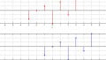
Figure 4. Turn-off characteristics of a power diode: (a) variation of forward current if, (b) variation of forward voltage drop vf, (c) variation of power loss
After the forward diode reaches zero, the diode continues to conduct in the opposite direction because of the presence of stored charges in the depletion layer and the p- or n-layer. The diode current flows for a reverse-recovery time (Trr or trr). It is the time between the instant forward diode current becoming zero and the instant reverse-recovery current decays to 25% of its reverse maximum value.
Where:
- Time ta: Charges stored in the depletion layer removed
- Time tb: Charges from the semiconductor layer are removed
- The shaded area in Figure 4a represents stored charges QR which must be removed during reverse-recovery time Trr.
As for the power loss across diode = vf * if (shown in Figure 4c), the major power loss in the diode occurs during the period tb. Altogether, recovery can be abrupt or smooth as shown in Figure 5.
.png)
Figure 5. Reverse-recovery characteristics for power diode
To know it quantitatively, we can use the softness factor (S-factor).
Where:
- Ratio tb/ta = S-factor
- S-factor = the measure of the voltage transient that occurs during the time the diode recovers
- S-factor 1 ⇒ low oscillatory reverse-recovery process (soft–recovery diode)
- S-factor <1 ⇒ large oscillatory overvoltage (snappy-recovery diode or fast-recovery diode)
Power diodes now exist with forward current rating of 1 A to several thousand amperes with reverse-recovery voltage ratings of 50 V to 5000 V or more.
Schottky Diode:
Regarding Schottky diodes (Figure 6), they typically have an aluminum-silicon junction where the silicon is an n-type.
.png)
Figure 6. Schottky diode symbol and current-voltage characteristics curve
As the metal has no holes, there is no stored charge and no reverse-recovery time. Therefore, there is only the movement of the majority carriers (electrons) and the turn-off delay caused by the recombination process is avoided. It can also switch off much faster than a p-n junction diode. As compared to the p-n junction diode it has:
- (a) Lower cut-in voltage
- (b) Higher reverse leakage current
- (c) Higher operating frequency
As for applications, these devices are typically used in high-frequency instrumentation and switching power supplies.
Metal-oxide-semiconductor Field-effect Transistor (MOSFET)
A MOSFET is a voltage-controlled majority carrier (or unipolar) three-terminal device. Its basic symbol is shown in Figure 7
.png)
Figure 7. MOSFET symbol
While Figure 8 shows the symbols for the different types of MOSFETs.
.png)
Figure 8. MOSFET symbols for different modes
As compared to the simple lateral channel MOSFET for low-power signals, a power MOSFET has a different structure. It has a vertical channel structure where the source and the drain are on the opposite side of the silicon wafer, as shown in Figure 9.
.png)
Figure 9. Cross-sectional view of the power MOSFET
This opposite placement of the source and the drain increases the capability of the power MOSFET to handle larger power.
In all of these connections, substrates are internally connected; however, in cases where it is connected externally, the symbol will change as shown in the n-channel enhancement type MOSFET (Figure 10). N-channel enhancement type MOSFET is more common due to the high mobility of electrons.
.png)
Figure 10. N-channel enhancement-type MOSFET with substrate connected externally
Next, let's introduce a basic circuit diagram of a power MOSFET (Figure 11).
.png)
Figure 11. Power MOSFET structural view with connections
On top of that, we'll also look at the output characteristics of an n-channel enhancement power MOSFET with the load connected, shown in Figure 12.
.png)
Figure 12. Drain current (ID) vs. drain-to-source voltage (VDS) characteristics curves
The drift region shown in Figure 11 determines the voltage-blocking capability of the MOSFET.
When VGS = 0, ⇒ VDD makes it reverse biased, and no current flows from drain to source.
When VGS > 0, ⇒ Electrons form the current path.
Thus, current from the drain to the source flows. If we increase the gate-to-source voltage, the drain current will also increase.
For a lower value of VDS, a MOSFET works in a linear region with a constant resistance equal to VDS / ID. For a fixed value of VGS and greater than threshold voltage VTH, the MOSFET enters a saturation region where the value of the drain current has a fixed value.
If XY represents the load line, then the X-point represents the turn-off point, and Y-point is the turn-on point where VDS = 0 (as a voltage across the closed switch is zero). The direction of the turning on and turning off process is also shown in Figure 13.
.png)
Figure 13. Output characteristics with load line
Besides the output characteristics curves, transfer characteristics of power MOSFET are also shown in Figure 14.
.png)
Figure 14. Gate-to-source voltage vs. drain current characteristics for power MOSFET
Here, VTH is the minimum positive voltage between the gate and the source above which MOSFET comes in on-state from the off-state. This is called threshold voltage which was shown in the output characteristics curve in Figure 12.
A close view of the structural diagram given in Figure 11 reveals that there exists a fictitious BJT and a fictitious diode structure embedded in the power MOSFET as shown in Figure 15.
.png)
Figure 15. Fictitious BJT and fictitious diode in the power MOSFET
As the source is connected to both base and emitter of this parasitic BJT, the emitter and base of the BJT are short-circuited. That means this BJT acts in a cut-off state.
A fictitious diode anode is connected to the source, and its cathode is connected to the drain. So, if we apply the negative voltage VDD across the drain and source, it will be forward-biased. That means the reverse-blocking capability of the MOSFET breaks. Thus, this can be used in inverter circuits for reactive loads without the need for excessive diode across a switch. Symbolically, it is represented in Figure 16.
.png)
Figure 16. MOSFET representation with internal body diode
Although MOSFET internal body diode has sufficient current and switching speed for most applications, there may be some applications where ultrafast diodes are required. In such cases, an external fast-recovery diode is connected in an antiparallel manner. But a slow-recovery diode is also required to block the body diode action as given in Figure 17.
.png)
Figure 17. Implementation of the fast-recovery diode for power MOSFET
One of the important parameters that affect the switching characteristics is the body capacitances existing between its three terminals i.e. drain, source and gate. Its representation is shown in Figure 18.
.png)
Figure 18. MOSFET representation showing junction capacitances
Parameters CGS, CGD, and CDS are all non-linear in nature and given in the device’s datasheet of a particular MOSFET. They also depend on the DC bias voltage and the device’s structure or geometry. They must be charged through the gate during the turn-on process to actually turn on the MOSFET. The drive must be capable of charging and discharging these capacitances to switch on or switch off the MOSFET.
Thus, the switching characteristics of a power MOSFET depend on these internal capacitances and the internal impedance of the gate drive circuits. Also, it depends on the delay due to the carrier transport through the drift region. Switching characteristics of power MOSFET are shown in Figure 19 and Figure 20.
.png)
Figure 19. Turn-on characteristics of power MOSFET
There is a delay from t0 to t1 due to the charging of input capacitance up to its threshold voltage VTH. Drain current in this duration remains at zero value. This is called a delay time. There is a further delay from t1 to t2 during which the gate voltage rises to VGS, a voltage required to drive the MOSFET into on-state. This is called the rise time. This total delay can be reduced by using a low-impedance drive circuit. The gate current during this duration decreases exponentially as shown. For the time greater than t2, the drain current ID has reached its maximum constant value I. As drain current has reached the constant value, the gate-to-source voltage is also constant as shown in the transfer characteristics of MOSFET in Figure 20.
.png)
Figure 20. Transfer characteristics of power MOSFET with operating point
For turn-off characteristics, assume that the MOSFET is already in the switched-on situation with a steady state. As t = t0, the gate voltage is reduced to zero value; CGS and CGD start to discharge through gate resistance RG. This causes a turn-off delay time up to t1 from t0 as shown in Figure 21. Assuming the drain-to-source voltage remains fixed. During this duration, both VGS and IG decrease in magnitude, and drain current remains at a fixed value drawing current from CGD and CGS.
.png)
Figure 21. Turn-off characteristics of power MOSFET
For the time where t2 > t > t1, gate-to-source voltage is constant. Thus, the entire current is now being drawn from CGD. Up to time t3, the drain current will almost reach zero value; which turns off the MOSFET. This time is known as the fall time, this is when the input capacitance discharges up to the threshold value. Beyond t3, gate voltage decreases exponentially to zero until the gate current becomes zero.
Power Bipolar Junction Transistor (BJT)
Power BJTs are used traditionally for many applications. However, IGBTs and MOSFETs have replaced them for most of the applications but still, but they are used in some areas due to their lower saturation voltage over the operating temperature range. IGBTs and MOSFETs have higher input capacitance as compared to BJT. Thus, in the case of IGBTs and MOSFETs, the drive circuit must be capable to charge and discharge the internal capacitances.
The BJT is a three-layer and two-junction NPN or PNP semiconductor device as given in Figures 22 (a) and (b).
.png)
Figure 22. (a) NPN BJT (b) PNP BJT
Although BJTs have lower input capacitance as compared to MOSFETs or IGBTs, BJTs are considerably slower in response due to low input impedance. BJTs use more silicon for the same drive performance.
In the case of MOSFET studied earlier, power BJT is different in the configuration as compared to simple planar BJT. In planar BJTs, the collector and emitter are on the same side of the wafer, while in power BJTs it is on opposite edges as shown in Figure 23. This is done to increase the power-handling capability of BJT.
.png)
Figure 23. Power BJT PNP structure
Power n-p-n transistors are widely used in high-voltage and high-current applications which will be discussed later.
Input and output characteristics of planar BJT for common-emitter configuration are shown in Figure 24. These are current-voltage characteristics curves.
.png)
Figure 24. Input characteristics and output characteristics for the common-emitter configuration of planar BJT, respectively.
Characteristic curves for power BJT are just the same except for the little difference in its saturation region. It has an additional region of operation known as quasi-saturation as shown in Figure 25.
.png)
Figure 25. Power BJT output characteristics curve
This region appears due to the insertion of a lightly-doped collector drift region where the collector-base junction has a low reverse bias. The resistivity of this drift region is dependent on the value of the base current. In the quasi-saturation region, the value of ß decreases significantly. This is due to the increased value of the collector current with increased temperature. But the base current still has control over the collector current due to the resistance offered by the drift region. If the transistor enters a hard saturation region, the base current has no control over the collector current due to the absence of the drift region and mainly depends on the load and the value of VCC.
A forward-biased p-n junction has two capacitances named depletion layer capacitance and diffused capacitance. While a reverse bias junction has only a depletion capacitance in action. The value of these capacitances depends on the junction voltage and construction of the transistor. These capacitances come into the role during the transient operation i.e. switching operations. Due to these capacitances, the transistor does not turn on or turn off instantly.
Switching characteristics of power BJT are shown in Figure 26. As the positive base voltage is applied, base current starts to flow but there is no collector current for some time. This time is known as the delay time (td) required to charge the junction capacitance of the base to the emitter to 0.7 V approx. (known as forward-bias voltage). For t > td, collector current starts rising and VCE starts to drop with the magnitude of 9/10th of its peak value. This time is called rise time, required to turn on the transistor. The transistor remains on so long as the collector current is at least of this value.
For turning off the BJT, the polarity of the base voltage is reversed and thus the base current polarity will also be changed as shown in Figure 26. The base current required during the steady-state operation is more than that required to saturate the transistor. Thus, excess minority carrier charges are stored in the base region which needs to be removed during the turn-off process. The time required to nullify this charge is the storage time, ts. Collector current remains at the same value for this time. After this, collector current starts decreasing, and base-to-emitter junction charges to the negative polarity; base current also gets reduced.
.png)
Figure 26. Turn-on and turn-off characteristics of BJT
Insulated-Gate Bipolar Transistor (IGBT)
IGBT combines the physics of both BJTs and power MOSFETs to gain the advantages of both worlds. It is controlled by the gate voltage. It has a high input impedance like a power MOSFET and has low on-state power loss as in the case of BJT. There is no even secondary breakdown and not have long switching time as in the case of BJT. It has better conduction characteristics as compared to MOSFET due to its bipolar nature. It has no body diode as in the case of MOSFET but this can be seen as an advantage of using an external fast recovery diode for specific applications. They are replacing the MOSFET for most of the high voltage applications with fewer conduction losses. Its physical cross-sectional structural diagram and equivalent circuit diagram are presented in Figure 27 to Figure 29. It has three terminals called collector, emitter, and gate.
.png)
Figure 27. IGBT structure view
There is a p+ substrate that is not present in the MOSFET and responsible for the minority carrier injection into the n-region. Gain of NPN terminal is reduced due to wide epitaxial base and n+ buffer layer.
There are two structures of IGBTs based on doping of the buffer layer:
a) Punch-through IGBT: Heavily doped n buffer layer ➔ less switching time
b) Non-Punch-through IGBT: Lightly doped n buffer layer ➔ greater carrier lifetime ➔ increased conductivity of drift region ➔ reduced on-state voltage drop
(Note: ➔ means implies)
.png)
Figure 28. Equivalent circuit for IGBT
.png)
Figure 29. Simplified equivalent circuit for an IGBT
.png)
Figure 30. Circuit diagram for an IGBT
Based on this circuit diagram given in Figure 30, forward characteristics and transfer characteristics are obtained which are given in Figure 31 and Figure 32. Its switching characteristic is also shown in Figure 33.
.png)
Figure 31. Forward characteristics for IGBT
.png)
Figure 32. Transfer characteristics of an IGBT
.png)
Figure 33. Turn-on and turn-off characteristics of an IGBT
(Note: Tdn : delay time ; Tr: rise time ; Tdf : delay time ; Tf1: initial fall time ; Tf2: final fall time)
Thyristors (SCR, GTO, MCT)
Thyristors are the family of solid-state devices extensively used in power electronics circuitry such as SCR (silicon-controlled rectifier), DIAC (diode on AC), TRIAC (triode on AC), GTO, MCT (MOS-controlled thyristor), RCT, PUT, UJT, LASCR, LASCS, SIT, SITh, SIS, SBS, SUS, SBS and etc. SCR is the oldest member and the head of this family; and is usually referred to with the name “thyristor”.
They are operated as bistable switches that are either working in a non-conducting or conducting state. Traditional thyristors are designed without gate-controlled turn-off capability in which the thyristor can come from conducting state to a non-conducting state when only the anode current falls below the holding current. While GTO is a type of thyristor that has a gate-controlled turn-off capability.
SCR
SCR usually has three terminals and four layers of alternating p and n-type materials as shown in Figure 34. The structure of the thyristor can be split into two sections: NPN and PNP transistors for simple analysis purposes as shown in Figure 36. It has three terminals named cathode, anode, and gate.
.png)
Figure 34. Structural view of thyristor
N-base is a high-resistivity region and its thickness is directly dependent on the forward blocking rating of the thyristor. But more width of the n-base indicates a slow response time for switching. The symbol of the thyristor is given in Figure 35.
_2.png)
Figure 35. Schematic symbol of thyristor
.png)
Figure 36. Two-transistor model of a thyristor (A-anode, G-gate, and K-cathode)
Planar construction is used for low-power SCRs. In this type of construction, all the junctions are diffused. For high power, mesa construction is used where the inner layer is diffused and the two outer layers are alloyed on it.
The static characteristic obtained from the circuit given in Figure 37 is drawn in Figure 38. It works under three modes: forward conducting mode, forward blocking mode, and reverse blocking mode.
The minimum anode current that causes the device to stay at forward conduction mode as it switches from forward blocking mode is called the latching current. If the SCR is already conducting and the anode current is reduced from forward conducting mode to forward blocking mode, the minimum value of anode current to remain at the forward conducting mode is known as the holding current.
.png)
Figure 37. Basic circuit for getting voltage and current characteristics of thyristor
.png)
Figure 38. Static characteristics curve of SCR
Switching characteristics of SCR are shown in Figure 39. Note that it can’t be turned off with the gate. This is due to positive feedback or a regenerative feedback effect.
.png)
Figure 39. Turn-on and turn-off characteristics of SCR
Gate Turn-off Thyristor
GTO can be turned on with the positive gate current pulse and turned off with the negative gate current pulse. Its capability to turn off is due to the diversion of PNP collector current by the gate and thus breaking the regenerative feedback effect.
Actually the design of GTO is made in such a way that the PNP current gain of GTO is reduced. Highly doped n spots in the anode p layer form a shorted emitter effect and ultimately decreases the current gain of GTO for lower current regeneration and also the reverse voltage blocking capability. This reduction in reverse blocking capability can be improved by diffusing gold but this reduces the carrier lifetime. Moreover, it requires a special protection as shown in Figure 43.
Figure 40 shows the four Si layers and the three junctions of GTO and Figure 41 shows its practical form. The symbol for GTO is shown in Figure 42.
.png)
Figure 40. Four layers and three junctions of GTO
.png)
Figure 41. Practical form of GTO
.png)
Figure 42. Symbol of GTO
Overall switching speed of GTO is faster than thyristor (SCR) but voltage drop of GTO is larger. The power range of GTO is better than BJT, IGBT or SCR.
The static voltage current characteristics of GTO are similar to SCR except that the latching current of GTO is larger (about 2 A) as compared to SCR (around 100–500 mA).
The gate drive circuitry with switching characteristics is given in Figure 43 and Figure 44.
.png)
Figure 43. Gate drive circuit for GTO
.png)
Figure 44. Turn-on and turn-off characteristics of GTO
MCT (MOS-Controlled Thyristor)
IGBT is an improvement over a BJT using a MOSFET to switch on or switch off the anode current. Similarly, MCT is an improvement over a thyristor with a pair of MOSFETs to switch the current. There are several devices in the MCT’s family but the p-channel is commonly discussed. Its schematic diagram and equivalent circuit is given in Figure 45 and Figure 46. Its symbol is given in Figure 47.
.png)
Figure 45. Schematic diagram of p-type MCT
.png)
Figure 46. Equivalent circuit for p-type MCT
.png)
Figure 47. Symbol of p-type MCT
Due to NPNP structure instead of PNPN, anode acts as a reference for gate. NPNP structure is represented by NPN transistor Q1 and a PNP transistor Q2 in the equivalent circuit.
The power required to switch it on or off is small with low switching losses due to its distributed structure across the entire surface of the device. Delay time due to charge storage is also small. It also has a low on-state voltage drop.
When a p-type MCT is in the forward-blocking state, it can be switched on by applying a negative pulse to its gate (with respect to anode). While when an n-channel MCT is in the forward-blocking mode, it can be switched on with the positive gate pulse (with respect to cathode). It will remain on until the device current is reversed or a turn-off pulse is applied to the gate i.e. applying a positive gate pulse for p-type MCT with respect to anode.
This device can bear a high current and high $$\frac{di}{dt}$$ capability. But just like any other devices, it needs to be protected against transient voltages and current spikes with the help of suitable snubbers. It is used in capacitor discharge applications, circuit breakers, AC-AC or AC-DC conversion. It is an ideal replacement for GTO as it requires a much simpler gate drive and certainly more efficient.


what is the “hole” with a transistor
Excellent. This article summarizes my entire semester in the power electronics course at the college. =)