 Facebook
 Google
 GitHub
 Linkedin
Amplify, Then Convert: A New High-Speed ADC Driver from Linear Tech
Good analog-to-digital conversion starts with good pre-ADC signal conditioning. Specialized devices such as the LTC6432-15 can help in this effort.
Good analog-to-digital conversion starts with good pre-ADC signal conditioning. Specialized devices such as the LTC6432-15 can help in this effort.
I think it is rather common these days to perform analog-to-digital conversion by simply connecting a signal directly to an analog input on, for example, an Arduino board. I don’t deny that this “works” in the sense that this approach will often result in reasonably accurate ADC data. However, this scheme should be the exception, not the rule.
In general, an ADC should be preceded by circuitry that makes the signal of interest more compatible with the process of digitization and with the characteristics of the ADC, itself.
Perhaps the most fundamental element in pre-ADC signal conditioning is the anti-aliasing filter. This is simply a low-pass filter that attenuates higher-frequency components and thereby minimizes aliasing.
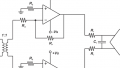
We also need to consider the characteristics of the ADC’s input and sampling circuitry. We may need to buffer the signal to ensure that the output impedance of the driver circuit is much lower than the input impedance of the ADC. (A convenient way to accomplish both filtering and buffering is to use an op-amp-based active filter.) One of my previous articles explores the ADC-input-impedance issue by means of an actual project involving the SAR ADC integrated into an EFM8 microcontroller.

A circuit representing the input stage of an EFM8 analog-to-digital converter.
Of course, the basic filter-plus-buffer approach is perhaps a little too primitive for today’s high-performance ADC applications. You have to be a bit more careful when you’re dealing with high resolutions and sampling rates up into the hundreds of megahertz.
A Dedicated Driver
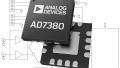
The LTC6432-15 from Linear Tech is intended specifically for driving high-resolution, high-speed ADCs. It has differential inputs and differential outputs, so you have to keep that in mind with regard to your interface circuitry and test equipment. The differential thing can be inconvenient but, overall, it’s a desirable feature because differential signaling is beneficial in terms of noise and distortion. Note also that the part needs a 5 V supply (i.e., 4.75–5.25 V); this restriction can catch you off guard nowadays since so many components accept supply voltages of 3.3 V or lower.
I don’t want to discourage you, but you actually do need a few external components when using the LTC6432-15:

Diagram taken from the LTC6432-15 datasheet.
I can’t speak to the actual amount of mental exertion involved in selecting these components, but let’s hope that Linear Tech is not placing undue burdens on innocent board designers. For me, this part became persona non grata as soon as I saw that it requires more than decoupling capacitors—and when I noticed that the external components include inductors, I promptly deleted the datasheet from my hard drive (just kidding).
(Very) High Speed
My feigned complaints about the external components become particularly absurd when you consider the performance offered by the LTC6432-15. The part is actually specified for operation up to 1.4 GHz; this is the kind of bandwidth we might need if, for example, we wanted to design a software-defined radio that digitizes the received RF signal or an IF signal instead of the baseband signal.
Low Noise
The LTC6432-15 combines this high-frequency performance with low-frequency performance: it maintains good noise, linearity, and gain characteristics down to 100 kHz. Certain applications would certainly appreciate this versatility, which is apparently attributable to the fact that the device is based on silicon-germanium (SiGe) instead of other semiconductor technologies that have more pink noise.
Two standard types of noise in electronic circuits are white noise and pink noise. White noise has constant spectral density (i.e., the amount of noise is more or less the same in all frequency bands). Pink noise, also called 1/f noise, exhibits an inverse relationship between spectral density and frequency: as frequency decreases, noise increases. This is reflected in the following plot for the LTC6432-15’s differential noise figure:

Plot taken from the LTC6432-15 datasheet.
As you can see, the part is optimized for signals from about 1 MHz to 200 MHz (at least in terms of noise).
Be Careful with Your Capacitors
Page 12 (PDF) of the LTC6432-15 datasheet has some interesting information regarding capacitor selection. The issue at hand is linearity.
You probably know that linearity is an important characteristic of high-frequency amplifiers. Nonlinearity leads to distortion, and distortion is manifested as undesirable harmonic components in the output signal. Linear Tech believes that the LTC6432-15 offers “incomparable” linearity and I’m in no position to disagree.
However, the wrong capacitors can compromise the LTC6432-15’s linearity performance. You can read the section for yourself; suffice it to say that Linear Tech recommends “automotive grade X8R” capacitors. This is good information because I, for one, typically use X7R and have never once in my life have I considered using X8R.
Do you have any tips or part recommendations for high-speed data-converter circuits? Let us know in the comments.
Related Content


Is there any ADC available of 20 bits or more?
You can joke about inductors, but design / selection of the right transformer (for that input) is not trivial. Neither are the potential problems when a 5V driver feeds a 3.3V (or less) ADC.