 Facebook
 Google
 GitHub
 Linkedin
Bridging the Gap Between Solid-State and Mechanical: The MEMS Switch
The ADGM1004 MEMS switch from Analog Devices is a high-performance solution for both low-frequency and high-frequency applications.
The ADGM1004 MEMS switch from Analog Devices, released in November, is a high-performance solution for both low-frequency and high-frequency applications.
The switch is undoubtedly one of the most fundamental electronic components. In the past, switches were placed into one of two categories: there were mechanical switches and solid-state switches. (I’ll continue using the generic term “switch,” though in this article we’re interested more specifically in relays—i.e., switches that can be actuated via circuitry instead of physical force.)
Both types have their advantages. Mechanical switches offer simplicity and versatility; you’re essentially dealing with a conductor that either does or does not establish a normal electrical connection between two terminals. Solid-state switches are semiconductor devices that allow current to flow based on the state of an input signal. They’re smaller, they offer faster switching and improved reliability, and they don’t bounce, but the on-state resistance is higher and I find myself annoyed by the less-straightforward implementation details.
Enter MEMS. A MEMS (microelectromechanical systems) device draws functionality from both the macroscopic and the microscopic world by combining IC technology with teeny tiny mechanical elements. There are MEMS gyroscopes, accelerometers, microphones—and switches.

Fast switching with MEMS: turn-on time less than 30 µs.
In this article, we’ll take a look at the new ADGM1004 (PDF) from Analog Devices. It’s an SP4T device that demonstrates the high performance that can be achieved through a MEMS approach to electrically controlled switching.

From (Very) Low to (Very) High Frequency
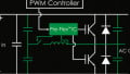
The ADGM1004 operates at frequencies up to 13 GHz. It’s no surprise, then, that the block diagram above gives you the impression that it’s more or less an RF component. However, it also works at DC and all frequencies in between. So, in reality, it’s a very-wide-band switch that is effective for RF applications as well as, for example, high-precision, low-frequency sensor interfaces.
Integrated Driver
The following diagram conveys the physical structure of the MEMS switch:

The connection is made by applying an electric field strong enough to move the cantilever beam. Note that typical mechanical relays use a magnetic rather than an electrostatic field; the electrostatic approach eliminates the need for an inductive element.
However, one little complication is that the voltages available from a typical digital circuit are not high enough to actuate the switch. As usual, though, IC technology allows the average designer to forget about this detail—the ADGM1004 includes charge-pump-based driver circuitry that boosts the control signals up to 80 V.
The above diagram indicates an inevitable limitation of the MEMS approach to switching: think how small that contact gap must be. You surely cannot expect to put a high (or even not so high) voltage across that tiny gap, but I think it’s pretty obvious that the part is intended for low-voltage applications.
Things to Keep in Mind
Overall I think that this MEMS switch offers an impressive combination of mechanical and solid-state characteristics. However, the MEMS approach is not without its imperfections.
Though MEMS technology enables higher reliability compared to typical mechanical switches, you have to be aware of the ADGM1004’s “continuously on lifetime” (PDF). Basically, if you leave the switch closed for a (very) long time, it may never open again. The limit here is about 7 years. So open your MEMS switch every year or two and hopefully everything will be fine.

Another failure mode is related to the “floating node” problem. As you know, a CMOS input terminal cannot be left floating, because charge can build up and cause spurious transitions. Well, the ADGM1004 has a similar issue. The switch nodes cannot be left floating because accumulating charge can eventually lead to actuation problems or even damage to the switch. This is not something you have to worry about with a typical mechanical switch.
And one last thing—don’t drop it. From the datasheet: “If the device is dropped during handling, do not use the device.”
Do you have any experience with MEMS switching? If so, feel free to leave a comment and tell us what you’ve learned.
All images used courtesy of Analog Devices. Featured image used courtesy of MEMX.


Pro’s & Cons, ADI’s ADGM1004 MEMS Switch
* Good:
————————-
* High IIP3: 67 dBm (typ.)
* Ins. loss: 0.45 dB (typ.) at 2.5 GHz
* Max. 32 dBm power.
* Bad:
————————-
* Approx. $35.00-$45.00 ea. in qty.-1K (ouch).
* Very Low 22 dB (min.), 24 dB (typ.) RF off isolation.
* Low 14-17 dB ret. loss (D6 GHz).
* On resistance: 1.8-3.5 Ohm (typ. 1.4 Ohm sw-sw var.)
* Con & Coff not specified above 1 MHz (but S-parms are supplied).
* Long 30 us on-switch time and 40 us settling time.
* 3-4 mA power consumption.
* Physically fragile & finnicky part.
* Complex 24-lead LFCSP package.
* Only 4xSPST parts available.
* Suggestions:
————————-
* Make these in 1xSPST standard package config. to allow switches to be physically and electrically isolated from each other (solves low on-die isolation problem). This approach will dramatically reduce the complex package and size, and reduce cost. Separating the switches into separate physical packages would allow for things like tunable filter components, and switch-able filters chains with high inter-filter isolation, things that are impossible with the product as it is today.
* Making a version of the switch SPDT with an on-die 50 ohm termination would go a long way to solving the poor switch-switch isolation. I think ADI has problems with this because the switch mechanical design is planar instead of linear. A linear mechanical design would also ensure all switch structures are embedded in the substrate, increasing isolation.
* Waaaay too expensive for even medium scale use!
Great article, Robert! And excellent use of the thumbnail image; it grabbed my attention immediatly, and drew me in to read the article.
Everything I get is dropped! I’m clumsy! No good. I’ll wait a few years until they get more reliable.