 Facebook
 Google
 GitHub
 Linkedin
Using Pressure Sensors to Adjust the Oxygen Concentration: An Electrical Engineer’s Intro to Mechanical Ventilation
In this article, we’ll look at additional applications of pressure sensors in mechanical ventilation.
Pressure sensors are key elements of mechanical ventilation. In a previous article, we discussed that a pressure sensor is required to monitor the airway pressure so that we can deliver breaths with specified pressure or flow profiles to the patient.
In this article, we’ll look at other applications of pressure sensors in mechanical ventilation. In addition to the common uses of pressure sensors, we’ll look at an interesting application of this type of sensor where pressure sensing is used to adjust the oxygen concentration in the air-oxygen mixture.
Pressure Sensors in Mechanical Ventilation
The block diagram of a ventilator is shown in the following figure. Please refer to my first ventilator article mentioned above for details.
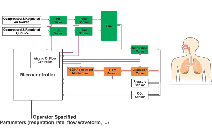
Figure 1. A block diagram of a ventilator.
Please note that the above image shows a simplified block diagram. Different ventilators may employ several other pressure sensors in addition to the one that measures the airway pressure. For example, some ventilators have internal regulators before the air and O2 valves. These ventilators may need a pressure sensor between the filter and the internal regulator as depicted in Figure 2.
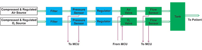
Figure 2. A ventilator block diagram utilizing a pressure sensor.
Moreover, ventilators usually need to measure the barometric pressure (the pressure of the atmosphere) to offset the undesired variations in measurements that may be caused by the physical location of the ventilator.
In addition to these relatively straightforward uses of pressure sensors, there are two other interesting applications for these sensors: adjusting the oxygen concentration in the air-oxygen mixture and measuring the flow of gas.
In this article, we’ll discuss the first application. Measuring gas flow using a pressure sensor will be discussed in a future article.
Using a Pressure Sensor to Adjust the Oxygen Concentration
While we can use an oxygen sensor to measure the oxygen concentration in the “tank”, there is another technique that detects the oxygen concentration by simply monitoring the gas pressure. To better understand this method, we need to first review a basic concept in chemistry called Dalton’s law of partial pressures.
But what is partial pressure?
Consider a mixture of two or more non-reactive gases kept in a container with a given volume. The pressure exerted by molecules of an individual gas is referred to as the partial pressure of that gas. In other words, partial pressure of each gas is the pressure that the gas would exert if it were the only gas in the container.
For example, assume that we have a mixture of O2 and N2 in a container as shown in Figure 3(a). The partial pressure of O2 is the pressure we get for the same number of O2 molecules with all N2 molecules removed as depicted in Figure 3(b).
We assume that the container volume and the temperature are not changed in this thought experiment.
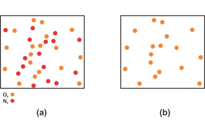
Figure 3. (a) A representation of a mix of O2 and N2. (b) The partial pressure remaining for the same O2 molecules with N2 removed.
Dalton’s Law of Partial Pressures
According to Dalton's law of partial pressures, the total pressure of a mixture of non-reactive gases is equal to the sum of the partial pressures of each constituent gas of the mixture.
In the above example, suppose that the partial pressures of oxygen and nitrogen are 2 atm and 1 atm, respectively. According to Dalton’s law of partial pressures, the pressure of the mixture will be:
\[P_{mixture}=P_{N2}+P_{O2}=1 \; atm + 2 \; atm = 3 \; atm\]
Ideal Gas Law
The ideal gas law is another basic concept in chemistry that we need to fully understand the oxygen concentration adjustment technique. According to the ideal gas law, the pressure P, volume V, and temperature T of a gas are related by the following equation:
\[PV=nRT\]
where n is the number of moles of the gas and R is the ideal gas constant which is \(0.08205 \frac {L \cdot atm}{mol \cdot K}\). Now, let’s see how we can use the above concepts to adjust the oxygen concentration.
Adjusting the Oxygen Concentration
The method we’ll discuss in this section is employed in a reference design from NXP. In this case, we remove the flow sensors that are included on the output side of the air and oxygen valves, and a pressure sensor is used to monitor the pressure of the tank.
Hence, the block diagram of this part of the ventilator is changed to the one shown in Figure 4.
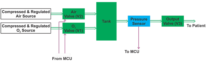
Figure 4. The ventilator block diagram without the flow sensors but with a pressure sensor.
Suppose that the gas mixture that is initially in the tank has a pressure of P1. For now, let’s not worry about the oxygen concentration of this initially stored gas. We just want to appropriately control the air and O2 valves so that the gas mixture that is going to be added to the tank has the right oxygen concentration.
We’ll divide the control process into two different phases:
- Phase 1, where oxygen is added, and
- Phase 2, in which air is conducted to the “Tank”.
Phase 1: Adding Oxygen
In this phase, we open the oxygen valve (V1) and close the air valve (V2). The oxygen valve will be open until the tank pressure increases from its initial value P1 to P2. The oxygen that we add in this phase—as well as the air that will be added in the next phase—will occupy the volume of the tank VT.
Assume that the tank temperature is TT. If we can determine the pressure of the added oxygen assuming that it is stored in a container with volume VT at a temperature of TT, we can apply the ideal gas equation to calculate the moles of added oxygen.
When this unknown amount of gas is added to the tank, the tank pressure increases from P1 to P2. Hence, based on Dalton’s law of partial pressures, we conclude that the partial pressure of the added oxygen is P2-P1.
Thus, when the volume of the added gas is VT, it exerts a pressure of P2-P1 at a temperature of TT. Applying the ideal gas equation, we have:
\[\left (P_2-P_1 \right )V_T=n_{O2}RT_T\]
Equation 1
where \(n_{O2}\) denotes the moles of added oxygen.
Phase 2: Adding Air
In this phase, we close the oxygen valve and open the air valve. The air valve will be kept open until the tank pressure increases from its previous value P2 to P3.
Air is a mixture of several gases such as nitrogen and oxygen, but for now, let’s assume that it consists only of nitrogen. With an analysis similar to that discussed above, we can apply the ideal gas equation and calculate the moles of added nitrogen:
\[(P_3-P_2)V_T=n_{N2}RT_T\]
Equation 2
where \(n_{N2}\) denotes the moles of added nitrogen. Dividing Equation 1 by Equation 2 gets us to
\[\frac {P_2-P_1}{P_3-P_2}=\frac {n_{O2}}{n_{N2}}\]
To have an oxygen concentration of A%, we should have:
\[\frac {P_2-P_1}{P_3-P_1}=\frac {n_{O2}}{n_{N2}+n_{O2}}= \frac {A}{100}\]
Hence, we obtain:
\[P_2=P_1+\left (P_3-P_1 \right ) \times \frac {A}{100}\]
Equation 3
This is the same as Equation 9 on Page 18 of the NXP reference design.
Let’s summarize the control procedure and then discuss its state diagram in detail. The control procedure starts with the tank pressure at P1. We add enough oxygen to increase the tank pressure to P2.
Next, air is conducted to the tank so that the tank pressure reaches a final value of P3. If we choose P2 based on Equation 3, the oxygen concentration should be A%.
State Diagram of Controlling the Valves
Based on the above discussion, we can use the state diagram shown in Figure 5 to control the valves.
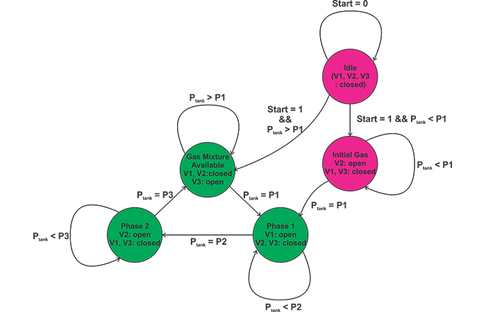
Figure 5
The magenta circles of this state diagram correspond to an initialization phase where the initial pressure of the tank is increased to P1 when the ventilator is turned on. The green circles implement the O2 concentration adjustment method that was described above.
Initialization Phase
Why do we need an initialization phase?
During the normal operation of the system, we know that the tank pressure should be between P1 and P3. However, imagine the very first time we turn on the ventilator. In this case, the tank pressure might be below P1.
Although this is probably a one-time case, we should take it into account in our state diagram. When the system is turned on and the tank pressure is below P1 (start=1 && Ptank < P1), the state machine goes to the “Initial Gas” state where the air valve (V2) opens to increase the tank pressure to P1.
Rather than filling the tank with air, we could alternatively fill it with oxygen during this initialization phase. Both options should work, because this specifies only the gas mixture initially stored in the tank. The amount of this gas should be much smaller than the gas that is added during the next phases of the state diagram. Hence, the mixture of the initial gas should have a minimal effect on the oxygen concentration after we go through a few cycles of adding oxygen and air with the appropriate proportions.
The "Gas Mixture Available" State
Now consider the case where we turn off the ventilator after it’s been in use for some time and then we turn it on again.
In this case, the initial pressure of the tank will be between P1 and P3. And, the tank will contain oxygen-enriched air. Therefore, when we turn on the system and observe that the tank pressure is greater than P1 (start=1 && Ptank > P1), the state machine should go to the “Gas Mixture Available” state. In this state, the output valve (V3) opens to supply the system with the required oxygen-enriched air.
While the system is in the “Gas Mixture Available” state, it will continuously check the tank pressure. As long as Ptank is greater than P1, the system has a sufficient amount of oxygen-enriched air, hence, it will remain in this state. When we deliver breaths to the patient, the tank pressure will gradually reduce. When the tank pressure reduces to P1 (Ptank = P1), we know that the tank is running out of sufficient oxygen-enriched air. Hence, the system should go to the “Phase 1” state where V1 opens to add oxygen to the tank. In this state, the output and the air valves (V2 and V3) are closed. We’ll stay in this state until the tank pressure reaches P2 given by Equation 3.
When Ptank=P2, the system will go to “Phase 2” to add air to the tank. This will open the air valve (V2) and close the oxygen and output valves (V1 and V3). The air will be added until the tank pressure reaches P3. At this point, the system is again able to supply the patient with the specified oxygen-enriched air. Hence, the state machine will go to the “Gas Mixture Available” state and the cycle will repeat.
The Main Limitation
The discussed technique mixes the gases from the two inputs with the specified percentage; however, this is not what we really want to achieve.
We should note that the desired parameter is the oxygen concentration which is only indirectly controlled by the above method. About 21% of air is oxygen, hence, we observe that “Phase 2” of the state diagram can contribute to the oxygen content of the tank as well.
Let’s repeat the above analysis assuming that 21% of air added in “Phase 2” consists of oxygen. Based on Equation 1, the moles of oxygen added during “Phase 1” is proportional to P2-P1:
\[n_{O2, Phase1}=\frac {\left (P2-P1 \right )V_T}{RT_T}\]
How many moles of oxygen are added during “Phase 2”? The gas mixture that is added in this phase increases the tank pressure by P3-P2. Since 21% of this gas is air, we can conclude that the moles of oxygen added in this phase is given by
\[n_{O2, Phase2}=0.21 \times \frac {\left (P_3-P_2 \right )V_T}{RT_T}\]
The total moles of oxygen will be:
\[n_{O2}=\left [\left (P_2-P_1 \right )+0.21 \times \left (P_3-P_2 \right ) \right ] \times \frac {V_T}{RT_T}\]
Equation 4
The moles of nitrogen added in “Phase 2” will be:
\[n_{N2}=0.79 \times \frac {\left (P_3-P_2 \right )V_T}{RT_T}\]
Equation 5
Dividing Equation 4 by Equation 5 gets us to:
\[\frac{n_{O2}}{n_{N2}}=\frac{\left (P_2-P_1 \right )+0.21 \times\left ( P_3-P_2 \right )}{0.79 \times \left (P_3-P_2 \right )}\]
To have an oxygen concentration of A%, we should have:
\[\frac{n_{O2}}{n_{N2}+n_{O2}}=\frac{\left (P_2-P_1 \right )+0.21 \times \left (P_3-P_ 2 \right )}{\left (P_3-P_1 \right )} =\frac{A}{10}\]
Hence, we obtain:
\[P_2=\frac{1}{0.79}\times \left [P_1-0.21 \times P_3+P_3-P_1 \times \frac{A}{100} \right]\]
Equation 6
Therefore, if we take the oxygen added in “Phase 2” into account, we should use Equation 6, which is considerably different from Equation 3. Furthermore, small variations in the oxygen content of the air supply would cause Equation 6 to become less accurate. Thus, the discussed method is limited by its inability to directly measure and control the oxygen concentration.
Conclusion
In this article, we looked at applications of pressure sensors in mechanical ventilation. In addition to the common uses of pressure sensors, we looked at an interesting application where pressure sensing is used to adjust the oxygen concentration in the air-oxygen mixture. We examined the mathematical derivations and the state diagram of the control process. The main limitation of this method is that it only makes sure that the gases from the two inputs are added with the specified percentage. And, it cannot directly control the oxygen concentration.
To see a complete list of my articles, please visit this page.
Related Content


This is all “well and good” and enables the mixture of two gases, BUT the oxygen concentration has to be measured (it is mandatory) because what if the two gases are nitrous oxide and air! The patient dies of hypoxia. These are safety-critical systems and we can not say these scenarios don’t happen because if they can they will and they have in the past, neonates have died on NICU and anaesthetised patients have died when nitrous has mistakenly been connected to oxygen supply lines. There is no place for surrogate measures of critical variables, if the actual variable can be measured. Paramagnetic oxygen analysers are very accurate for oxygen concentration and we are duty bound to measure the resultant oxygen concentration of any delivered gas mixture. Thus the feed back loop will correct any errors in volume mix. Modern anaesthetic/ICU machines use very low volumes of gases to create the inspiratory gas mixture and this method will only be approximate.