 Facebook
 Google
 GitHub
 Linkedin
An Engineer’s Introduction to Mechanical Ventilation
Learn about the basics of mechanical ventilation in terms of subsystems, control loops, and algorithms.
In this article, we’ll examine the basic operation of a ventilator in the terminology of control systems, sensors, and microcontrollers. Then, we’ll examine the block diagram of a basic ventilator in greater detail. Please note that this article is intended to explore the design of ventilators from a high level and does not represent a medical explanation of ventilator use and operation.
What Is a Ventilator?
A ventilator is a control system where the output is a flow of oxygen-enriched air with certain specifications. A mechanical ventilator is a machine that assists a patient's breathing during surgery or in situations where they cannot breathe on their own due to a critical illness.
A ventilator is a relatively complex system that employs several valves and sensors along with a processing unit to implement the required control algorithms.
Basic Operation of a Ventilator
A typical ventilator system consists of three main sub-systems:
- The “Inspiratory Flow Delivery System” is responsible for generating and manipulating the oxygen-enriched air that is sent into the patient’s lungs.
- The “Expiratory Path” that provides an appropriate path for the exhalation.
- A microcontroller (MCU) is used to control the operation of the whole system based on the information obtained from different sensors and the parameters that the clinician specifies.
You can see the basic operation of a ventilator illustrated in Figure 1.

Figure 1. Basic positive-pressure ventilator operation
As shown in the figure, the ventilator is connected to compressed sources of air and oxygen. Using these supplies of gas, the inspiratory path generates a flow of oxygen-enriched air. Several parameters of the delivered air—such as its pressure, volume, flow, and oxygen percentage—are of interest and should be controlled by the ventilator.
Positive-Pressure vs. Negative-Pressure Respirators
The ventilator depicted in Figure 1 is usually referred to as a positive-pressure ventilator because it applies inspiratory air with a pressure greater than the atmospheric pressure (positive pressure) to push air into a patient’s airway.
In contrast, a negative-pressure ventilator produces the inspiratory flow by generating a negative pressure around the patient’s chest. Negative-pressure ventilators have several limitations and are not as common these days.
Modes of Operation
Ventilators have different modes of operation such as volume-controlled ventilation, pressure-controlled ventilation, etc. Depending on the selected mode of operation, the ventilator should be able to deliver inspiratory air with pressure, volume, or flow waveforms consistent with some predefined desired waveforms.
For example, Figure 2 shows the pressure and flow waveforms for the pressure-controlled mode of operation where the ventilator keeps the patient’s airway pressure at a given level for the entire duration of inspiration. It should be noted that, in practice, the system might not be able to perfectly follow these desired waveforms because of different system non-idealities and noise sources.

Figure 2. Waveforms for describing the pressure and flow of air through a ventilator
The example waveforms depicted in the above figure correspond to a relatively simple mode of operation where the ventilator operates independently from the patient’s respiratory reaction. In reality, we need more sophisticated interactions between the ventilator and the patient.
In case the patient initiates a breath, a sophisticated ventilator will be able to synchronize its operation with this change. From the implementation point of view, this requires more complicated algorithms to control the valves within the system as well as a fast-response control loop. These can be some of the key differences between a sophisticated ventilator and a simpler one.
Block Diagram of a Ventilator
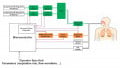
The block diagram of a basic ventilator is shown in Figure 3.

Figure 3. Block diagram of a ventilator
Inspiratory Flow Delivery System
The green blocks in Figure 3 correspond to the “Inspiratory Flow Delivery System” in Figure 1. This path is connected to regulated sources of air and oxygen. Ventilators may have internal regulators, as well (not shown in Figure 3). These internal regulators are used to reduce the gas pressure provided by the air and oxygen source to a lower level suitable for the ventilator.
As shown in Figure 3, the air and oxygen sources are connected to valves and flow sensors. The MCU monitors the output of the flow sensors and controls the valves accordingly. In this way, the ventilator produces oxygen-enriched air with a specified oxygen concentration and conducts it to the “Tank”. During inspiration, the ventilator opens the “Inspiration Valve” and closes the “Expiration Valve”. The “Inspiration Valve” is controlled in a way that the patient receives breaths consistent with the desired predefined waveforms.
As you can see, the key factor is adjusting the valves so that different system parameters (such as oxygen concentration, flow, and pressure) meet the specifications. To achieve this, we can employ controller design strategies such as the proportional-integral-derivative (PID) control technique. Figure 3 shows the control loop for adjusting the air and oxygen valves.
Expiratory Path
During expiration, the ventilator opens the “Expiration Valve” and closes the “Inspiration Valve”. The exhaled air goes through the “Flow Sensor” and the “PEEP Adjustment Mechanism” where PEEP stands for positive end-expiratory pressure. The output of the flow sensor is monitored by the MCU to achieve the sophisticated ventilator–patient interactions that were discussed above.
PEEP is the positive pressure in the lungs that exists at the end of expiration (by "positive" we mean that the pressure is greater than the atmospheric pressure). With the example waveforms depicted in Figure 2, the pressure at the end of expiration is zero (PEEP is zero); however, we sometimes prefer to keep the airway pressure above the atmospheric level during expiration (non-zero PEEP). This keeps the patient's lungs from collapsing.
There are several methods to create a non-zero PEEP. An efficient technique is simply placing an electronically-controlled valve in the expiratory path. This dynamic resistance partially occludes the path of the exhaled air so that the airway pressure remains at the desired level. Figure 4 shows the structure of such a valve.

Figure 4. An example electronically-controlled valve. Image courtesy of Alex Yartsev
Sensors
In addition to the blocks that we have discussed so far, a ventilator needs a few other devices. A pressure sensor and a CO2 sensor are required to monitor the airway and provide the patient with sophisticated output waveforms and features.
Moreover, since the moisture of compressed gas sources is removed, we need a humidifier to add moisture to the oxygen-enriched air that is delivered to the patient (the humidifier is not shown in our block diagram).
In addition, a ventilator should have a graphical display to show appropriate settings, measurements, calculations, and alarms.
Conclusion
A mechanical ventilator is a relatively complex system that employs several valves and sensors along with a processing unit to implement the required control algorithms.
Depending on the selected mode of operation, the ventilator should be able to deliver inspiratory air with pressure, volume, or flow waveforms consistent with some predefined desired waveforms. Hence, a ventilator is a control system where the output is a flow of oxygen-enriched air with certain specifications.
To see a complete list of my articles, please visit this page.
Related Content


Not to be critical as this is a good basic summary. However, so that reality is acknowledged, this is a very over-simplified approach to mechanical ventilation. For example, the PEEP valve has not been a mechanical restrictor for many years and now is usually a counter flow pressure device impeding exhalation. All ventilators are safety-critical systems, not just simple PID servo mechanisms. The modes of ventilation are many, not just pressure generators. They will typically be pressure generators, volume generators, pressure generators with volume guarantee, etc etc, there will be controls over inspiratory time, inspiratory hold, inspiratory to expiratory time ratio and many many more variables. There is the view out there that a company like Tesla or Virgin can engineer a ventilator in a week! These instruments are connected to patients, a simple error, a failure of loop control, or sensor malfunction can lead to barotrauma, pneumothorax or even death. But most of all a simple solution (although a good ventilator for anaesthesia for example) will not help Covid 19 patients, these individuals have complex changes to their respiratory mechanics which a non-complex machine can not match (in the days of simple ventilators in ICU, when the ventilator couldn’t cope the patient died), it is a testament to the medical engineers that produce these complex machines that have improved ICU outcomes. What we need is for the companies like GE, Draeger, Siemens etc to Open Source their designs (unlikely as they charge $10,000’s of dollars per machine!) for the betterment of the community.
Good article for a newcomer like me.