Facebook
 Google
 GitHub
 Linkedin
Eliminate Brushes, Reduce Noise: A New Motor-Driver IC from ROHM
You can improve performance in motor-control applications by using brushless DC motors and handy driver ICs such as the BU69090NUX.
You can improve performance in motor-control applications by using brushless DC motors and handy driver ICs such as the BU69090NUX.
I think most engineers these days understand that a typical brushed DC motor is a very convenient and very noisy device. The brushes accomplish polarity reversal, aka “commutation,” such that you can make the motor turn by simply applying a constant DC voltage. But the abrupt connections and disconnections associated with these brushes result in transient disturbances that can affect the circuit connected to the motor (via standard conduction pathways) as well as nearby components (via EMI).
The obvious solution is to eliminate the brushes, and that approach leads to a brushless DC motor. The question is: How do we make the motor turn without brushes that provide ongoing polarity reversal?
The general idea is to commutate using electronics instead of mechanical devices. As you know, motors are frequently driven by full-bridge circuits; these consist of four transistors arranged so that current supplied by a DC voltage source can be driven through a load in either direction. Thus, we can reverse the polarity of a motor’s magnetic field even though the supply for the drive circuitry is always positive:

The difficulty here is that you need to know when to reverse the polarity. Synchronization occurs automatically inside a brushed DC motor, but if we are using electronics instead of brushes, we need some sort of feedback regarding the position of the rotor. One way to obtain this feedback is via a hall-effect sensor.
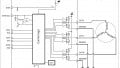
Controller + Bridge + Hall
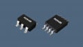
The BU69090NUX (we’ll call it the 6909) from ROHM is described as a single-phase motor driver for laptop cooling fans, though surely some creative readers could find additional (and perhaps somewhat less mundane) applications.

Diagram taken from the BU69090NUX datasheet.
The hall element is physically inside the IC package. Thus, you can’t use the 6909 to drive a motor on the other side of the room. As I was looking through the datasheet I didn’t see any specific information on the necessary physical relationship between the IC and the motor. I find this a bit surprising; perhaps the people who typically design laptop cooling fans already know where they’re going to put the driver chip. The rest of us, I suppose, will have to contact ROHM or experiment.

The datasheet does provide this magnetic-polarity orientation diagram, but I don’t know what to do with it. If you have any ideas, or if you’re appalled at my ignorance, feel free to scroll down and leave a comment.
The 6909 is a single-phase device because it has one full bridge for driving one motor winding. This is in contrast to a three-phase brushless DC motor, which has three windings and therefore requires three drive circuits governed by a carefully devised commutation scheme.
The Hall Signal
It takes more than just a Hall element to accomplish brushless DC motor control. You can see in the block diagram that the Hall signal passes through an offset cancellation block and is then digitized. Another feature not explicitly shown in the diagram is automatic gain control (AGC).
My understanding is that the amplitude of the feedback signal will vary, perhaps significantly, according to the characteristics of the motor and the distance between the motor and the chip. The AGC makes the 6909 more versatile and user-friendly by ensuring that it can automatically compensate for these unpredictable variations. This rather busy diagram visually conveys the AGC functionality:

Diagram taken from the BU69090NUX datasheet.
Speed Control
Adjusting motor speed is essential in many applications, so it’s no surprise that the 6909 incorporates this functionality as well. DC motors are typically driven by a fixed voltage source, so we can’t control rotational speed by changing the actual drive voltage. Instead, we vary the average voltage delivered to the winding by pulse-width modulating the output of the driver circuit.
The 6909’s speed control is implemented via a PWM input pin that (indirectly) controls the PWM duty cycle of the motor-drive signal.

Diagram taken from the BU69090NUX datasheet.
The PWM characteristics of the output signal are more complicated than those of the input signal. The following diagram is quite informative with regard to how the 6909 actually works:

Diagram taken from the BU69090NUX datasheet.
- The polarity of the OUT1/OUT2 motor-drive signals reverses in conjunction with the changes in detected magnetic polarity.
- The FG output signal can be used to inform another component about the state of the motor.
- The input PWM controls the output PWM, but the frequencies are not the same, and the output PWM changes before and after the transition events (this is referred to as the “soft-switching” functionality).
Do you have any ideas for projects that could benefit from a motor-driver IC like the BU69090NUX? If so, you can share your thoughts in the comments section.