Facebook
 Google
 GitHub
 Linkedin
FM Demodulation with Feedback: Exploring Threshold Reduction Mechanisms
By closing a feedback loop around the demodulator, the FMFB architecture narrows the noise bandwidth and lowers the FM threshold, without improving SNR at high CNR.
In FM systems, the threshold effect limits how low the transmitted power can go for a given set of specifications. This drives particular interest in reducing the noise threshold to achieve optimal performance at minimal signal power. Two widely used demodulator configurations that reduce the noise threshold are the FM demodulator with negative feedback (FMFB) and the PLL demodulator. These architectures are commonly known as extended-threshold demodulators. This article examines the core mechanisms of the FMFB circuit, focusing on its method for FM demodulation and its ability to extend the noise threshold.
High Noise Bandwidth Problem in Slope Detectors
Before exploring the FMFB demodulator, it’s important to understand why most FM demodulators exhibit relatively high noise levels. Consider the simple slope detector FM demodulator depicted in Figure 1 below.
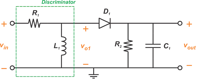
Figure 1. FM demodulation using an RL circuit as a frequency discriminator
The RL circuit in the demodulator above performs FM-to-AM conversion (Figure 2). Then, the envelope detector recovers the message signal.
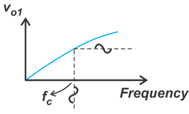
Figure 2. The voltage-frequency characteristic of the RL discriminator.
FM demodulator circuits, such as the slope detector, that utilize the FM-to-AM conversion principle incorporate circuits with a bandwidth equal to or greater than that of the FM wave. As a result, the discriminator is exposed to all the noise contained within the FM wave’s bandwidth, which typically exceeds the message bandwidth significantly (Carson’s rule). A high noise level at the discriminator input can trigger a sudden, severe drop in FM signal quality due to the threshold effect.
FMFB Demodulator
The FMFB demodulator, shown in Figure 3 below, forms a feedback path around the conventional FM demodulator to reduce the effective noise bandwidth at the discriminator input.
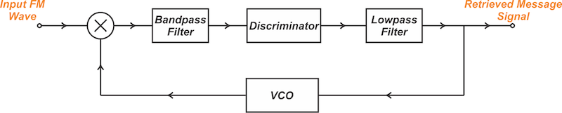
Figure 3. FM demodulation using a feedback mechanism.
The FMFB demodulator consists of a standard FM demodulation structure that incorporates a VCO and mixer to route the output back to the input. Ahead of the discriminator is an IF bandpass filter with center frequency ωIF and bandwidth wide enough to pass the FM signal undistorted. Finally, the lowpass filter restricts the output bandwidth to that of the message signal, removing the out-of-band noise components, thereby minimizing the noise at the output.
Prior to assessing noise performance, how does the above circuit perform FM demodulation? One way to understand the operation of the FMFB circuit as an FM demodulator is to note that, with sufficient loop gain, the operation performed in the forward path of the feedback system is the inverse of the operation performed in the return path. The return path is a voltage-controlled oscillator (VCO) which can serve as an FM modulator. Therefore, the forward path should perform FM demodulation. For a deeper understanding of the FMFB circuit’s operation, we must go beyond this conceptual view and develop the governing equations. Let’s begin by analyzing the VCO and constructing its mathematical model.
VCO Behavior and Mathematical Representation
Figure 4 shows a conceptual representation of the VCO, with input and output signals labeled.

Figure 4. A conceptual view of the VCO.
The total argument of the VCO output sinusoid can be expressed as:
$$\phi_{total}(t) = \omega_0 t + \phi_{ex}(t)$$
Equation 1
where ω0 is the free-running frequency of the VCO and ϕex(t) is the excess phase term. The free-running frequency represents the output frequency when the control voltage vcont(t) is zero or held constant, reflecting the natural oscillation rate of the VCO in the absence of modulation caused by the input.
The excess phase term captures the time-varying deviation from the nominal phase due to the control voltage. This term reflects how the VCO responds dynamically to changes in its input signal vcont(t). The concept of excess phase is central to understanding how circuits with VCOs operate. It’s typically assumed to relate to the control voltage as follows:
$$\phi_{ex}(t) = k_{vco} \int_0^{t} v_{cont}(t) \ dt$$
Equation 2
where the constant kvco is the VCO gain factor measured in radians per second per volt (rad/sV). Applying the Laplace transform to Equation 2 yields the VCO’s transfer function, relating its input voltage to the excess phase at the output in the frequency domain, as shown below:
$$H(s) = \frac{\Phi_{ex}}{V_{cont}}(s) = \frac{k_{vco}}{s}$$
Equation 3
While Equations 2 and 3 form the foundation for analyzing the FMFB circuit, it’s worthwhile to derive the VCO’s instantaneous frequency for a more complete picture of its behavior. Combining Equations 1 and 2, the total phase or the argument of the VCO output sinusoid can be rewritten as:
$$\phi_{total}(t) = \omega_{0} t + k_{vco} \int_0^{t} v_{cont}(t) \ dt$$
Equation 4
Noting that frequency is the time derivative of phase, we can differentiate the above equation to find the instantaneous output frequency of the VCO:
$$\omega_{vco}(t) = \omega_0 + k_{vco} v_{cont}(t)$$
Equation 5
As observed, the instantaneous output frequency of the VCO is offset from its free-running frequency ω0 by an amount proportional to the VCO’s control voltage vcont.
FMFB Demodulation Mechanism
Figure 5 presents the FMFB demodulator with some additional details.
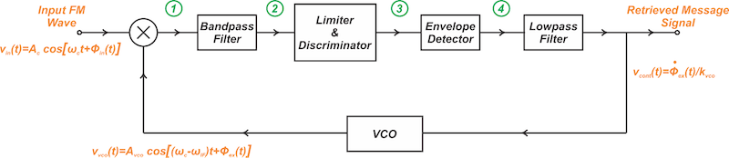
Figure 5. FMFB demodulator featuring annotated signal details.
Assume the input FM signal takes the form:
$$v_{in}(t) = A_c \ cos[\omega_c t + \phi_{in}(t)]$$
Equation 6
where:
Ac is the amplitude of the input FM wave
ωc is the carrier frequency
ϕin(t) is the message-dependent phase term.
The FMFB demodulator uses a VCO whose free-running frequency ω0 is ωc-ωIF, where ωIF is the center frequency of the bandpass filter following the mixer.
When two sinusoidal waves are applied to a multiplier mixer, the output contains frequency components equal to both the sum and difference of the input frequencies. Therefore, the signal at the output of the mixer is:
$$\begin{eqnarray}v_{1}(t) &=& v_{in}(t) \times v_{vco}(t) \\&=& A_c \ A_{vco} \ cos[\omega_c t + \phi_{in}(t)] \times cos[(\omega_c - \omega_{IF})t + \phi_{ex}(t)] \\&=& \frac{1}{2} A_c \ A_{vco} \Big ( cos \big [\omega_{IF} t + \phi_{in}(t) - \phi_{ex}(t) \big ] + cos \big [(2 \omega_c - \omega_{IF}) t + \phi_{in}(t) + \phi_{ex}(t) \big ] \Big) \end{eqnarray}$$
Equation 7
This output is then passed through a bandpass filter centered at ωIF, with a sufficiently narrow bandwidth to pass the difference frequency while rejecting the sum frequency. Note how choosing the appropriate free-running frequency for the VCO causes the difference frequency term produced at the mixer output to match the bandpass filter’s center frequency.
Assuming a filter gain factor of k1, the bandpass filter produces the following signal at node 2:
$$v_{2}(t) = \frac{1}{2} A_c \ A_{vco} k_1 \Big ( cos \big [\omega_{IF} t + \phi_{in}(t) - \phi_{ex}(t) \big ] \Big)$$
Equation 8
The above angle-modulated signal is applied to the limiter-discriminator. Since the limiter removes any amplitude variations, we infer that the signal produced by the limiter has a known amplitude, which we take to be unity. Additionally, the discriminator functions as a differentiator. Therefore, neglecting the amplitude of v2(t), we take its time derivative to obtain the discriminator output:
$$v_{3}(t) = - \alpha \Big [\omega_{IF} + \frac{d}{dt} \big [ \phi_{in}(t) - \phi_{ex}(t) \big ] \Big ] \times \Big [ sin \big [\omega_{IF} t + \phi_{in}(t) - \phi_{ex}(t) \big ] \Big]$$
Equation 9
where ⍺ denotes the gain factor of the discriminator. After applying envelope detection and eliminating the constant term ωIF using a DC blocker, the output signal is:
$$v_{cont}(t) = \alpha \times \frac{d}{dt} \big [ \phi_{in}(t) - \phi_{ex}(t) \big ]$$
Equation 10
where the lowpass filter is assumed to have a unity gain factor. However, the VCO operation described by Equation 2 provides an alternative expression for the relationship between ϕex(t) and vcont(t). Differentiating Equation 2, we have:
$$v_{cont}(t) = \frac{1}{k_{vco}} \times \frac{d}{dt}\phi_{ex}(t)$$
Equation 11
By combining Equations 10 and 11, we derive the following:
$$\alpha \times\frac{d}{dt} \big [ \phi_{in}(t) - \phi_{ex}(t) \big ] = \frac{1}{k_{vco}} \times \frac{d}{dt}\phi_{ex}(t)$$
Equation 12
which simplifies to:
$$\frac{d}{dt} \phi_{ex}(t) = \frac{\alpha \times k_{vco}}{1 + \alpha \times k_{vco}} \times \frac{d}{dt}\phi_{in}(t)$$
Equation 13
Finally, by substituting the above equation into the expression for vcont(t) (Equation 11), we obtain:
$$v_{cont}(t) = \frac{\alpha}{1 + \alpha \times k_{vco}} \times \frac{d}{dt}\phi_{in}(t)$$
Equation 14
Recall that ϕin(t) represents the phase of the input FM wave, which is proportional to the integral of the message signal. Since ⍺ is the gain factor of the conventional demodulator incorporated in the forward path, we observe that the VCO control voltage produces the desired term—⍺ times the derivative of ϕin(t)—but attenuated by the factor 1/(1 +⍺kvco).
How Does the FMFB Demodulator Reduce Noise Threshold?
To grasp how the FMFB demodulator reduces noise, it’s essential to understand how the feedback mechanism alters the deviation ratio of the FM wave. According to Equation 8, the phase term of the signal component passing through the bandpass filter is ϕin(t)-ϕex(t). Meanwhile, Equation 12 establishes the following relationship between ϕin(t) and ϕex(t):
$$\phi_{ex}(t) = \frac{\alpha \times k_{vco}}{1 + \alpha \times k_{vco}} \times \phi_{in}(t)$$
Equation 15
Consequently, the difference term entering the bandpass filter is:
$$v_{1,\ diff}(t) = \frac{1}{2} A_c \ A_{vco} \times cos \big [\omega_{IF} t + \frac{1}{1+ \alpha k_{vco}} \times \phi_{in}(t) \big ]$$
Equation 16
which is centered at ωIF and has a phase term of ϕin(t)/(1+⍺kvco). The IF bandpass filter must have sufficient bandwidth to pass this FM wave. If we compare Equation 16 with the input FM wave, we observe that the feedback configuration reduces the deviation ratio by a factor of 1/(1+⍺kvco). According to Carson’s equation below, the FM signal bandwidth BT scales roughly with the deviation ratio:
$$B_T = 2(D+1)W$$
Equation 17
Therefore, the required bandwidth of the IF bandpass filter in the FMFB demodulator is reduced by a factor of 1/(1+⍺kvco) compared to an FM demodulator operating without feedback. This ultimately decreases the noise within the system and lowers the threshold for FM detection.
SNR Performance of FMFB at High Carrier-to-Noise Ratios
An essential point in understanding the FMFB circuit is how its feedback mechanism influences the output SNR at high carrier-to-noise ratio (CNR) values. Figure 6 shows that both the conventional demodulator and the FMFB circuit yield the same SNR when the input CNR is high.
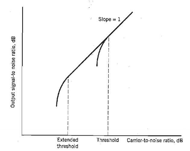
Figure 6. The FMFB demodulator reduces the threshold, but it doesn’t affect SNR at high CNR values. Image used courtesy of Simon Haykin
When first encountering the FMFB demodulator, it may seem counterintuitive that lowering the threshold value doesn’t affect the SNR in high-CNR conditions. In the next article, we’ll delve into this topic in great detail and provide some solved examples to solidify the concepts discussed above.
Wrapping Up
The FMFB demodulator introduces a feedback loop around the conventional FM demodulator, effectively narrowing the noise bandwidth at the discriminator input. This reduction in bandwidth lowers the noise threshold for FM detection. However, despite the lowered threshold, the FMFB demodulator doesn’t alter the SNR in high-CNR conditions.
Feature image background used courtesy of Adobe Stock