 Facebook
 Google
 GitHub
 Linkedin
Introduction to Reactance Modulators for Generating FM Signals
In this article, we'll introduce the fundamental concepts of direct FM generation and examine a key FM modulation circuit: the reactance modulator.
Several types of modulators are used to generate FM signals. In some, the modulating signal directly changes the frequency of the carrier wave. Other types, which we'll discuss later in this series of articles, use phase modulation as an intermediate step before converting to FM.
In all cases, FM signal generation requires a circuit with a variable output frequency. This output frequency needs to change in direct proportion to the message signal's instantaneous amplitude. The instantaneous frequency should vary solely based on the amplitude of the message signal and be independent of the message signal's frequency. Finally, an ideal FM modulator should maintain a constant carrier frequency.
Once we recognize that an FM modulator is a circuit with a variable output frequency, it's easy to see that an LC oscillator with adjustable capacitance or inductance can serve as an FM modulator. In Hartley and Colpitts oscillators, for instance, the frequency of oscillation is given by:
$$\omega_0 ~=~ \frac{1}{\sqrt{LC}}$$
Equation 1.
We therefore seek ways to create voltage-controlled capacitances or inductances suitable for incorporation into our LC oscillator. We also need to make sure that the frequency changes are directly proportional to the amplitude of the message signal.
A Simple FM Generator
In this article, our primary focus will be on a circuit known as the reactance modulator. Along with the varactor diode, it's one of the two most popular methods of producing adjustable reactances for direct FM generation. However, as shown in Figure 1, a very simple FM generator can also be constructed using a capacitor microphone placed in parallel with the tank circuit of an LC oscillator. The frequency of oscillation is determined by the capacitor and inductor in the tank circuit.

Figure 1. A capacitor microphone used to generate FM waves.
In the above circuit, a capacitor microphone (also known as a condenser microphone) serves as the capacitance of the tank circuit. The capacitance of this type of microphone varies with the sound wave striking it. The sound wave's amplitude therefore controls how much the oscillator's frequency deviates from its center value. The frequency of the sound wave is what determines the rate of frequency variations at the oscillator output.
Although instructive, the capacitor microphone FM system is seldom used in practice because it lacks adequate frequency stability and can't achieve the frequency deviation needed for practical applications. For that reason, the reactance modulator technique is much more widely used.
The Reactance Modulator
The reactance modulator uses a transistor and passive components to create a variable reactance. This variable reactance, which can be capacitive or inductive, is used to change the LC oscillator's tank circuit. A basic reactance modulator is shown in Figure 2.
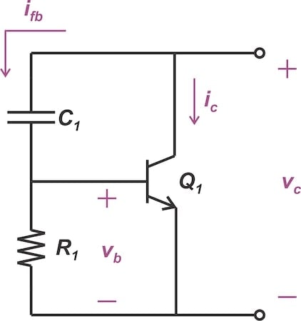
Figure 2. A basic reactance modulator.
Note that the reactance modulator can be built around either a BJT or FET device.
In this circuit, capacitor C1 and resistor R1 are used to provide feedback from the collector to the base of the transistor. For C1, we opt for a small value to ensure its reactance at the frequency of interest is considerably higher than the resistance of R1. As a result, the current flowing through the R1C1 branch is essentially set by the capacitor.
Ignoring the base current, we can approximate the feedback current (ifb) by:
$$i_{fb} ~=~ \frac{v_c}{\frac{1}{jC_1 \omega}}~=~v_c ~\times~ jC_1 \omega$$
Equation 2.
The voltage at the base of the transistor is obtained as:
$$v_b ~=~ R_1 ~\times~ i_{fb} ~=~ v_c ~\times~ jR_1C_1 \omega$$
Equation 3.
If the transistor's transconductance is gm, the resulting collector current is:
$$i_c ~=~ g_{m}v_{b} ~=~ v_c ~\times~ jg_{m}R_1C_1 \omega$$
Equation 4.
Assuming that ifb is negligible relative to ic, we can now calculate the impedance as seen from the collector:
$$Z_{eq} ~\approx~ \frac{v_{c}}{i_c} ~\approx~ \frac{1}{j \omega g_{m}R_1C_1 } ~=~ \frac{1}{j \omega C_{eq}}$$
Equation 5.
The impedance viewed from the collector then corresponds to an effective capacitance of:
$$C_{eq} ~=~ g_{m} R_1 C_1$$
Equation 6.
As this equation illustrates, the equivalent capacitance can be set to a proper initial value by choosing the correct values for R1 and C1.
Insights From the Reactance Modulator Analysis
Regarding the above analysis, one important observation is that choosing a small capacitance in the R1C1 branch is vital to the circuit's functionality. Since the impedance of the capacitor C1 is much higher than R1, the voltage appearing at the base terminal (vb) leads the collector voltage (vc) by 90 degrees (Equation 3). Consequently, the collector current (ic) leads vc by 90 degrees, which is essential for having an overall capacitive impedance.
It's also worth noting that our simplified analysis disregarded R1 when calculating ifb. Without this simplification, we obtain:
$$i_{fb} ~=~ \frac{v_c}{R_{1}~+~\frac{1}{jC_1 \omega}} \quad \rightarrow \quad v_b ~=~ \frac{R_1}{R_{1}+\frac{1}{jC_1 \omega}} ~\times~ v_c$$
Equation 7.
In this case, the collector current is:
$$i_c ~=~ \frac{g_{m}R_1}{R_{1}~+~\frac{1}{jC_1 \omega}} ~\times~ v_c$$
Equation 8.
Assuming that ifb ≪ ic, we determine the impedance viewed from the collector as:
$$Z_{eq} ~=~ \frac{1}{g_m}~+~ \frac{1}{jg_{m}R_{1}C_{1} \omega}$$
Equation 9.
The term 1/gm in the above equation signifies that the circuit also produces a resistive component that changes with gm and thus with the message signal. This variable resistance changes the quality factor of the tank circuit, leading to some unintended amplitude modulation. To minimize the amplitude modulation effect, it may be necessary to place an amplitude limiter after the oscillator.
Using a Reactance Modulator for FM Generation
From Equation 6, we know that the equivalent capacitance of the circuit depends on the transistor's transconductance (gm). Therefore, the effective capacitance can be varied by the bias voltage applied to the base terminal, with the circuit serving as a voltage-controlled capacitance. Figure 3 illustrates how the collector and emitter terminals of the reactance modulator can be connected to an LC oscillator to construct a tunable oscillator.
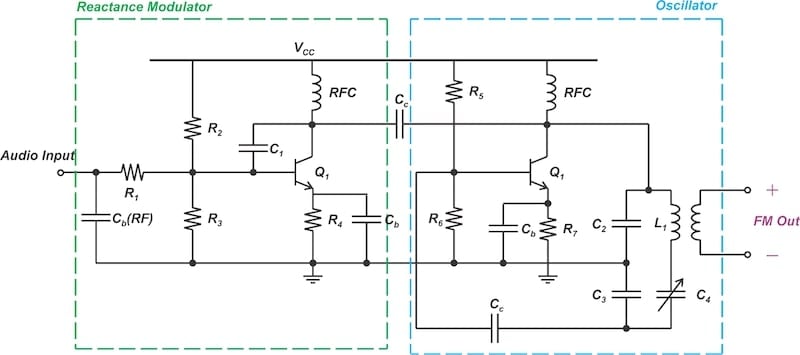
Figure 3. A reactance modulator connected to a Clapp-Gouriet oscillator.
Figure 3 employs a Clapp-Gouriet oscillator, which is a variation of the Colpitts oscillator. As noted, the modulating signal is applied to the base terminal, altering the transconductance and the effective capacitance (Ceq). In this way, it generates an FM wave.
Constructing a Voltage-Controlled Inductor
If we reverse the positions of R1 and C1 in Figure 2, the resulting circuit produces an inductive reactance. This is illustrated in Figure 4.

Figure 4. A reactance modulator circuit arranged to produce an inductive impedance.
In this case, the reactance of C1 needs to be much smaller than the resistance of R1. With R1 being the dominant impedance in the R1C1 branch, the current ifb is calculated as:
$$i_{fb} ~\approx~ \frac{v_c}{R_{1}}$$
Equation 10.
As this current passes through C1, it generates a base voltage of:
$$v_{b} ~=~ i_{fb} ~\times~ \frac{1}{j C_{1} \omega} ~\approx~ \frac{v_c}{j R_{1} C_{1} \omega}$$
Equation 11.
This produces a collector current of:
$$i_{c} ~=~ g_{m} v_{b} ~\approx~ \frac{g_{m}}{j R_{1} C_{1} \omega} ~\times~ v_c$$
Equation 12.
Now, assuming that ifb is negligible compared to ic, we can determine the effective impedance as viewed from the collector:
$$Z_{eq} ~=~ \frac{v_{c}}{i_{c}} ~\approx~ j ~\times~ \frac{R_1 C_1}{g_m} ~\times~ \omega$$
Equation 13.
This corresponds to an effective inductance of R1C1/gm, which is clearly dependent on the transistor's transconductance. When using a reactance modulator to build a variable inductor, we may need a DC blocking capacitor in series with R1, as illustrated in Figure 5.

Figure 5. An inductive reactance modulator may require a DC blocking capacitor in the feedback path.
Capacitor C2 doesn't significantly impact the modulator's reactance; it merely prevents the collector's DC level from influencing the gate bias. Additionally, remember to factor in the Miller effect when computing the equivalent capacitance that appears at the transistor's base terminal.
Wrapping Up
In a direct FM system, the modulating signal directly alters the frequency of the carrier oscillator. This requires an LC oscillator with adjustable capacitance or inductance. In this article, we learned how a reactance modulator circuit accomplishes this using only a transistor and a few passive components.
As the message signal changes the variable reactance, it leads to a corresponding adjustment in the resonant frequency of the carrier oscillator. In this way, the reactance modulator can provide the large frequency deviation needed for practical applications. In the next article, we'll calculate this frequency deviation. We'll then extend our discussion to include other reactance modulator circuits suitable for direct FM generation.
This article is Part 1 of a seven-part series on FM signal generation. All articles in this series are listed below in order of publication:
- Introduction to Reactance Modulators for Generating FM Signals
- An FM Generator Circuit Using the Capacitance of a Collector-Base Junction
- Using Varactor Diodes for FM Signal Generation
- Improving the Frequency Deviation and Stability of a Direct FM Generator
- Understanding Varactor and PLL-Based FM Generation Using Crystal Oscillators
- Armstrong's Method of FM Generation
- FM Generation Techniques: Solved Examples
All images used courtesy of Steve Arar
Related Content


“the capacitor microphone FM system is seldom used in practice because it lacks adequate frequency stability and can’t achieve the frequency deviation needed for practical applications.”
Actually, both Sennheiser and Rodes supply these. They’re used for sound transduction in high-humidity environments.