Facebook
 Google
 GitHub
 Linkedin
Improving the Frequency Deviation and Stability of a Direct FM Generator
In this article, we explore the limitations of LC oscillators for direct FM generation and how to deal with them using multipliers and automatic frequency control (AFC) circuits.
In this series of articles, we've discussed multiple ways of creating a variable reactance for direct FM generation. In all cases, the variable reactance was used to modulate an LC oscillator. However, a direct FM generator using a single, non-crystal oscillator will fail to maintain adequate carrier frequency stability.
In this article, we'll learn how an automatic frequency control (AFC) circuit can be employed to ensure that the center frequency drift of the FM generator is minimal. We'll also explore how frequency multipliers can enhance the frequency deviation of a direct FM generator.
The Challenge of Direct FM Generation
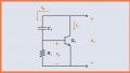
Figure 1 shows how a varactor in parallel with an oscillator's resonant circuit can be incorporated to generate FM waves.
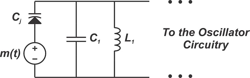
Figure 1. Using a varactor to build a tunable oscillator for FM generation.
The direct FM generation circuit shown in Figure 1 needs to satisfy two conflicting requirements:
- Its instantaneous frequency must quickly respond to the modulating signal.
- The center frequency of oscillation must maintain long-term stability.
Achieving these two goals using a single oscillator can be challenging. As we'll discuss in a future article, one way to overcome this fundamental challenge is to use an indirect FM generator. An indirect FM generator doesn't require the carrier oscillator to respond to a modulating signal.
Another method of stabilizing the carrier frequency involves using a feedback configuration. This is commonly known as automatic frequency control. The AFC loop aims to increase the center frequency stability without using a crystal in the main oscillator of the modulator.
We'll come back to AFC later in the article. For now, let's discuss how frequency multipliers and mixers help us obtain the desired frequency deviation and carrier frequency.
Using Frequency Multipliers to Boost FM Frequency Deviation
A reactance modulator operating at 5 MHz might have a frequency deviation of ±4 kHz, which is significantly lower than the ±75 kHz maximum deviation used in commercial FM broadcasting. As illustrated in Figure 2, we can increase the frequency deviation by using a frequency multiplier.
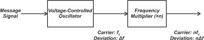
Figure 2. To increase the frequency deviation, we add a frequency multiplier after the VCO.
A frequency multiplier generates an output signal whose frequency is an exact multiple of its input frequency. If we apply a sinusoid with argument θi to a frequency multiplier with multiplication factor of n, the output sinusoid's argument would be nθi. As a result, by applying an FM signal to an n-fold frequency multiplier, we can increase its frequency deviation by a factor of n.
For instance, say that a modulator produces an FM signal with a carrier frequency of 5 MHz and a maximum frequency deviation of ±4 kHz. By applying a ×18 frequency multiplication, we achieve an FM wave with a carrier frequency of 5 MHz × 18 = 90 MHz and frequency deviation of ±4 kHz × 18 = 72 kHz. These values are much closer to what's required in commercial FM broadcasting.
Frequency multiplication is typically carried out in steps of ×2 or ×3. The circuits used for this are known as doublers and triplers, respectively. For ×18 frequency multiplication, we can cascade two triplers and a doubler, as shown in Figure 3.

Figure 3. Implementing a ×18 multiplier by cascading two triplers and one doubler.
Creating Frequency Multipliers With Nonlinear Circuits
To achieve frequency multiplication, the input signal is fed through a nonlinear component, which distorts the signal and generates harmonics (integer multiples of the input frequency). A bandpass filter then selects the desired harmonic frequency and removes the unwanted frequency components—including the fundamental—from the output.
Figure 4 depicts a simplified model of a frequency doubler where a Class C amplifier serves as the nonlinear circuit and an LC tank tuned to the second harmonic provides the required bandpass filtering. Since the input FM wave's carrier frequency is 5 MHz, the output tank circuit is tuned to 10 MHz.
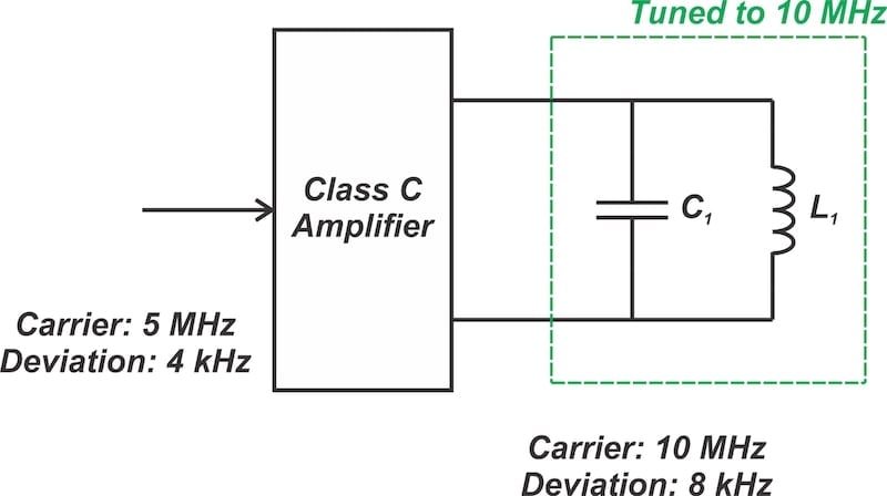
Figure 4. A frequency doubler built around a Class C amplifier.
Using Mixers for Frequency Translation
As we previously observed, a frequency multiplier raises both the carrier frequency and the frequency deviation of the FM wave. Using a large multiplication factor to achieve the target frequency deviation may result in a center frequency much higher than what we're aiming for. In such cases, a mixer can be used to reduce the carrier frequency. The mixing operation does not affect the frequency deviation.
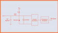
Figure 5 is the block diagram of an FM generator that includes frequency multipliers and mixers after the VCO to obtain the desired carrier frequency and frequency deviation.

Figure 5. A direct FM generator that includes multipliers and a mixer after the VCO.
Improving Frequency Stability With AFC
Direct FM generation can generally achieve the desired frequency deviation with minimal frequency multiplication. However, direct methods often suffer from poor frequency stability. To address this, we can use feedback loops to provide automatic frequency control (AFC).
In the AFC loop, the center frequency of the output FM wave is compared to a constant frequency produced by a crystal oscillator. The error signal, which is proportional to the frequency difference, is then fed back to the oscillator to correct the discrepancy. This system is illustrated in Figure 6.

Figure 6. Using a frequency-locked loop to stabilize the center frequency.
In Figure 6, the output of the VCO is mixed with a crystal oscillator. The difference frequency at the output of the mixer is extracted and applied to a frequency discriminator. A frequency discriminator is a circuit that converts the frequency variations of an FM signal into corresponding voltage amplitude variations at the output. The signal from the frequency discriminator is filtered with a lowpass filter and subsequently used to adjust the voltage-controlled oscillator.
The Frequency-Locked Loop
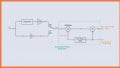
To better understand the AFC operation, let's consider the frequency stabilization loop in Figure 7.

Figure 7. An example of a frequency stabilization loop.
In this example, the output of the VCO is an FM wave with a carrier frequency of 5.1 MHz. This frequency is multiplied by a total factor of 3 × 2 × 3 = 18, generating an output carrier of 91.8 MHz. The output of the ×2 multiplier, which has a carrier frequency of 5.1 MHz × 3 × 2 = 30.6 MHz, is also applied to the mixer. The other input of the mixer is produced by a crystal-controlled oscillator at 14.3 MHz followed by a ×2 multiplier, resulting in a stable oscillation frequency of 28.6 MHz.
A mixer generates two distinct frequency components at its output. One frequency component is the sum of the input frequencies; the other is the difference between the input frequencies. The circuit in Figure 7 employs a bandpass filter to extract the difference frequency component. The output is subsequently fed into a frequency discriminator set to the difference frequency, which in this case is 2 MHz.
The feedback loop described above is a frequency-locked loop. It's closely related to the phase-locked loop, which will be covered in future articles. For a more thorough analysis of this AFC configuration, I recommend the book "Communication Circuits: Analysis and Design" by Donald T. Hess and Kenneth K. Clarke.
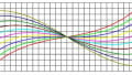
The ideal frequency-to-voltage response of a frequency discriminator tuned to 2 MHz is illustrated in Figure 8. The discriminator generates an output voltage proportional to the input frequency, providing the opposite functionality of a VCO.

Figure 8. The ideal frequency-to-voltage response of a frequency discriminator tuned to 2 MHz.
Note that the discriminator is tuned to produce 0 V when its input is at 2 MHz. With a stable reference frequency from the crystal oscillator, a 2 MHz difference frequency corresponds to the intended carrier frequency of 5.1 MHz at the output of the VCO. When the target carrier frequency is generated (fc = 5.1 MHz), the discriminator provides 0 V, and the feedback loop doesn't modify the VCO.
The feedback loop doesn't affect the VCO when it's at the desired carrier frequency. However, if there's a deviation in the oscillation frequency, the loop outputs a DC voltage with the appropriate polarity at the lowpass filter's output to adjust and return the oscillation frequency to the desired carrier frequency.
It's worth mentioning that the lowpass filter following the frequency discriminator limits the bandwidth of the feedback loop so that it doesn't respond to the relatively fast frequency variations caused by the message signal. Instead, it only responds to the slow drift of the master oscillator. If this weren't the case, the feedback loop would negate the message-induced frequency changes, preventing the generation of FM waves.
Wrapping Up
In this article, we expanded our understanding of direct FM generation by exploring the role of frequency multipliers in enhancing frequency deviation. We also highlighted the limitations of non-crystal oscillators in maintaining carrier frequency stability. As we learned, the implementation of an automatic frequency control (AFC) circuit is essential to address these limitations and minimize center frequency drift. This discussion underscores the importance of precise frequency control in the effective generation of FM waves.
This article is Part 4 of a seven-part series on FM signal generation. All articles in this series are listed below in order of publication:
- Introduction to Reactance Modulators for Generating FM Signals
- An FM Generator Circuit Using the Capacitance of a Collector-Base Junction
- Using Varactor Diodes for FM Signal Generation
- Improving the Frequency Deviation and Stability of a Direct FM Generator
- Understanding Varactor and PLL-Based FM Generation Using Crystal Oscillators
- Armstrong's Method of FM Generation
- FM Generation Techniques: Solved Examples
All images used courtesy of Steve Arar
Related Content