 Facebook
 Google
 GitHub
 Linkedin
Introduction to Frequency Discriminators for FM Demodulation
In this article, we will examine the basic principles of FM demodulation through the simplest frequency discriminator: a differentiator.
Frequency demodulation is the process of recovering the original message signal from a frequency-modulated (FM) wave. But how do we accomplish this? One method is to first convert the FM signal into an amplitude-modulated (AM) wave. An envelope detector is then used to recover the message signal.
A circuit that translates frequency changes in an FM signal into corresponding voltage changes is known as a frequency discriminator or frequency detector. In this article—the first in a new series on FM demodulation—we'll learn about a simple demodulation system that uses a differentiator for frequency discrimination. As the name suggests, a differentiator is a circuit whose output is proportional to the derivative of the input.
The Simplified FM Demodulator
Figure 1 illustrates the basic concept of the FM demodulator we'll discuss in this article.
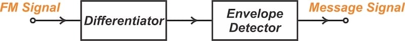
Figure 1. Simplified block diagram of an FM demodulator that employs a differentiator.
To understand how this circuit works, consider the FM signal described by:
$$s_{FM}(t) ~=~ A_c \cos \big [ 2 \pi f_c t ~+~ 2 \pi k_f \int_{0}^{t} m(\alpha) d \alpha \big ]$$
Equation 1.
Assuming that the amplitude (Ac) is constant, the time derivative of the signal is:
$$\frac{d}{dt} \big (s_{FM}(t) \big ) ~=~ -A_c \Big ( 2 \pi f_c ~+~ 2 \pi k_f m(t) \Big ) ~\times~ \sin \big [ 2 \pi f_c t ~+~ 2 \pi k_f \int_{0}^{t} m(\alpha) d \alpha \big ]$$
Equation 2.
In Equation 2, the amplitude and angle are modulated by the message signal. Ignoring the negative sign, the envelope of the signal is:
$$Envelope ~=~ 2 \pi A_c f_c \Big ( 1 ~+~ \frac{k_f m(t)}{f_c} \Big )$$
Equation 3.
Since the carrier frequency (fc) is typically much greater than kfm(t), the envelope of the signal is identical to that of a conventional AM signal. We then use an envelope detector to restore the message signal from the obtained AM signal. It should be noted that since fc ≫ kfm(t), small fluctuations in the carrier frequency don't significantly impact the envelope detector's output.
How Does Differentiation Perform FM-to-AM Conversion?
A differentiator multiplies the input spectrum by jω = j2πf in the frequency domain. The frequency response of an ideal differentiator can be described by:
$$H( \omega) ~=~ j \omega K$$
Equation 4.
where K is a constant. Therefore, for an ideal differentiator, the magnitude response increases linearly with frequency, while the phase response remains constant at 90 degrees.
But how does this convert FM to AM? From Equation 1, it's easy to show that the FM wave's instantaneous frequency (fi) changes in accordance with the message signal, m(t), as described by the following equation:
$$f_i ~=~f_c~+~k_f m(t)$$
Equation 5.
Assuming that kf > 0, an increase in the instantaneous frequency occurs when the amplitude of m(t) increases. In this way, the variations in the frequency mirror the variations in the amplitude of the message signal.
If we then pass this FM signal through a circuit that boosts the output as the input frequency increases, we can transform the variations in instantaneous frequency back into variations in output amplitude. For instance, consider applying the FM wave to the transfer function shown in Figure 2.
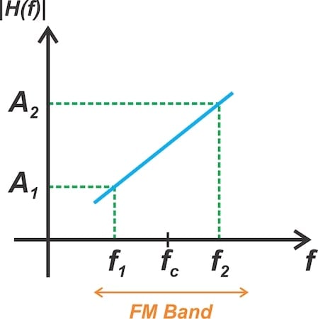
Figure 2. A frequency response suitable for FM-to-AM conversion.
When the instantaneous frequency is f1, the output amplitude is A1. As the instantaneous frequency changes from f1 to f2, the output amplitude linearly increases from A1 to A2. A transfer function of the form:
$$|H(f)|~=~2 \pi af~+~b$$
Equation 6.
can therefore be used to perform FM-to-AM conversion.
There are many circuits for realizing the differentiator. An RL circuit might be the simplest example. A bandpass filter, such as a tuned LC circuit, can also approximate a differentiator over a narrow frequency range. This is why a detuned AM receiver can partially demodulate FM signals using slope detection.
Understanding the Demodulator Waveforms
Figure 3 illustrates the waveforms of an FM demodulator that uses a differentiator.
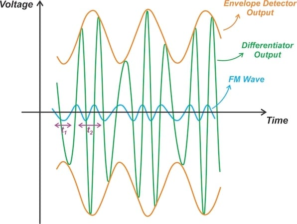
Figure 3. Typical waveforms of an FM demodulator built around a differentiator.
To understand these waveforms, consider the time intervals t1 and t2. In the above figure, these are marked in purple.
During the time interval t2, the FM wave (blue curve) exhibits a higher instantaneous frequency than it did in the preceding interval (t1). The rapid variations during t2 result in a higher signal amplitude at the differentiator's output (green curve) compared to the amplitude during t1. By passing the differentiator output through an envelope detector, we obtain the message signal (orange curve).
To help us visualize this, Figure 4 shows demodulator waveforms created using Matlab for the following example values:
- m(t) = cos(2π × 4 × t)
- fc = 60 Hz
- kf = 20 Hz/V.

Figure 4. The message signal (top), the corresponding FM wave for fc = 60 Hz, and kf = 20 Hz/V (middle), and the derivative of the FM wave (bottom).
In the above figure, the top waveform represents the message signal. The middle waveform illustrates the corresponding FM wave. Finally, the bottom waveform depicts the derivative of the FM wave.
While the input signal to the differentiator is an FM wave with constant amplitude, the output signal from the differentiator is a hybrid-modulated signal in which both the amplitude and frequency vary with the message signal.
The Complete FM Demodulation System: Limiter and DC Block
To keep things simple, we've been assuming that the amplitude of the FM wave is constant. It's easy to see that when using a differentiator for FM-to-AM conversion, unwanted amplitude variations at the input will affect the output. This means that noise, signal fading, and other factors that cause undesired amplitude modulation at the input will distort the recovered message signal.
To eliminate the amplitude modulation from noise and channel distortions, we can use a limiter before the discriminator. The transfer characteristic of an ideal limiter is shown in Figure 5.
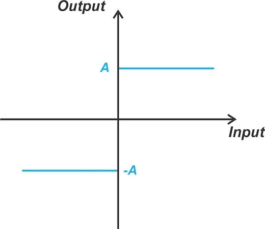
Figure 5. Transfer characteristic of an ideal hard limiter.
When the sinusoidal modulated wave passes through the hard limiter, it's transformed into a frequency-modulated square wave. The hard limiter clips the signal to remove unwanted amplitude variations. However, we now need a bandpass filter tuned to the carrier frequency to select the right harmonic from the square wave's spectrum. This leads to the demodulator block diagram shown in Figure 6.

Figure 6. Incorporating a hard limiter to eliminate unwanted amplitude modulation.
To represent a working FM demodulator, the above block diagram needs one more modification: incorporating a DC block at the output. The final block diagram incorporating the DC block is depicted in Figure 7.

Figure 7. The complete FM demodulator block diagram.
From Equation 3, we know that the envelope of the signal produced by the differentiator is positive because the carrier frequency (fc) is typically much greater than kfm(t). This allows us to use a simple envelope detector as an AM demodulator.
However, the recovered envelope, described by Equation 3, yields a scaled and DC-shifted version of the message signal. It is essential to use AC coupling after the envelope detector to reject the DC term and obtain a scaled version of the message signal, just as in conventional AM.
While using AC coupling allows us to get rid of the envelope's DC term, it also attenuates very low-frequency components of the message signal. In later articles in this series, we'll learn about demodulator circuits that eliminate the envelope's DC term without using AC coupling.
Wrapping Up
A frequency discriminator is a device whose output amplitude is directly proportional to the instantaneous frequency of the incoming FM wave. Often in practical circuits for FM-to-AM conversion, the transfer function only has a linear slope near the carrier frequency. It's important to note that some references use the term "frequency discriminator" to describe the slope circuit, while others apply it to the entire modulator system, including both the slope circuit and the subsequent envelope detector.
FM demodulators require a limiter to remove unwanted amplitude modulation at the input. Additionally, some demodulators require a DC block at the output to eliminate the constant term of the envelope caused by the carrier frequency.
This article is Part 1 of a five-part series on FM demodulator circuits. All articles in this series are listed below in order of publication:
- Introduction to Frequency Discriminators for FM Demodulation
- Understanding Slope Detectors for FM Demodulation
- FM-to-AM Conversion Using the Foster-Seeley Discriminator
- Basic Principles and Implementation of the Quadrature FM Demodulator
- FM Demodulation Using a Phase-Locked Loop
All images used courtesy of Steve Arar
Related Content


Thank you for the great articles