 Facebook
 Google
 GitHub
 Linkedin
FM Demodulation Using a Phase-Locked Loop
PLL demodulators are popular, easy to implement, and offer superior noise performance compared to many other FM demodulator circuits. Learn how they operate in this article.
Phase-locked loops (PLLs) are negative feedback systems extensively utilized in modern communication systems for carrier and symbol synchronization, frequency synthesis, and as core components of numerous digital demodulators. In this article, we'll focus on PLLs for FM demodulation.
Noise Improvement Through Feedback Demodulators
Before we discuss the PLL demodulator, we'll consider two other circuits so that we have a basis for comparison. Figure 1(a) shows the first of these, a simple FM demodulator that uses an RL circuit as a frequency discriminator. As we see in Figure 1(b), the RL circuit exhibits an almost linear magnitude response near the carrier frequency (fc).
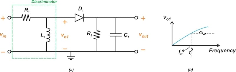
Figure 1. FM demodulation using a slope detector (a) and the voltage-frequency characteristic of the RL discriminator (b).
In the above demodulator, the RL circuit performs FM-to-AM conversion. An envelope detector then retrieves the message signal.
FM demodulators that utilize FM-to-AM conversion incorporate circuits with a bandwidth equal to or greater than that of the FM wave. Consequently, the demodulator circuit allows all the noise within the FM wave's bandwidth to pass through.
To address this issue, we can use an alternative method that involves placing a frequency modulator in the return path of a feedback system. This is known as an FM demodulator with feedback (FMFB). An example of such a system is shown in Figure 2.
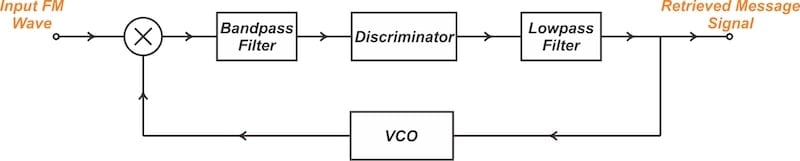
Figure 2. FM demodulation using a feedback mechanism.
To understand the operation of the FMFB circuit, note that with sufficient loop gain, the operation performed in the forward path of the feedback system is the inverse of the operation performed in the return path. Here, the return path is a voltage-controlled oscillator (VCO). Since the VCO can serve as an FM modulator, the forward path should perform FM demodulation.
As we mentioned earlier, the output bandwidth of the slope detector in Figure 1 matches that of the FM wave. The intermediate-frequency bandpass filter used in the FMFB configuration, however, has a bandwidth comparable with the message bandwidth. This is advantageous because the message bandwidth is commonly much narrower than the FM wave bandwidth. According to Carson's rule, the FM wave bandwidth can be estimated by:
$$BW ~=~ 2(\beta ~+~ 1)f_m$$
Equation 1.
where β is the modulation index and fm is the message signal frequency. For instance, with fm = 300 Hz and β = 10, the FM wave bandwidth works out to BW = 6.6 kHz. Since the FMFB circuit narrows the noise bandwidth at the discriminator's input, it lowers the noise threshold for FM detection.
In the rest of the article, we'll discuss how to implement a feedback FM demodulator using a PLL. Due to the popularity of the PLL and its availability as an integrated-circuit device, we'll explore it in greater detail than the configuration in Figure 2.
The PLL FM Demodulator
Figure 3 shows the block diagram of a basic PLL.
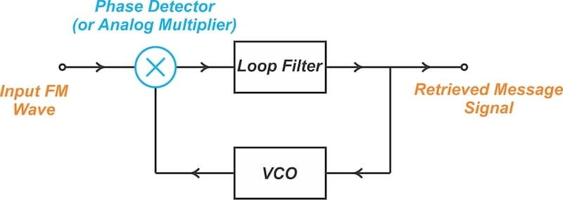
Figure 3. Basic block diagram of a PLL used for FM demodulation.
As we see above, a PLL comprises three key components arranged in a feedback loop: a phase detector, a lowpass filter, and a VCO. The phase detector compares the phase of the input signal with that of the VCO output, generating a signal that varies with the phase difference. This signal is then passed through a lowpass filter to produce the VCO's control voltage.
If the VCO output is ahead of the PLL input in phase, the control voltage retards the VCO output phase. Conversely, when the VCO output is behind the PLL input in phase, the control voltage is adjusted to advance the VCO output phase. In this way, the PLL forces the VCO output phase to follow that of the input FM wave. Note that a fixed phase difference of 90 degrees arises when using a multiplier-type phase detector.
The pertinent question is this: how can forcing a VCO to follow the input FM wave perform demodulation? To answer this, we should note that the PLL demodulator is closely related to the direct method of FM generation, where the frequency of an oscillator is directly altered in accordance with the message signal. Figure 4 shows the simplified block diagram of a direct FM generator.
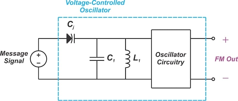
Figure 4. Simplified block diagram illustrating direct FM generation.
In principle, a VCO is all we need to directly produce FM waves, provided the VCO's output frequency has a linear relationship with its control voltage.
The PLL-based method of FM demodulation reverses the modulation process by using a negative feedback structure to force the output of the oscillator to follow the input FM wave. Since the VCO output reproduces the input FM wave, its control voltage must vary in accordance with the underlying message signal.
A major advantage of PLL demodulators is that they can achieve better noise performance than most FM demodulators. While the VCO output needs to match the FM wave's bandwidth, its control voltage, restricted by the preceding lowpass filter, should have a bandwidth corresponding to the message signal. As with the FMFB configuration we discussed earlier, this reduction in signal bandwidth helps improve the demodulator's noise performance.
Mathematical Analysis of the PLL Demodulator
The input FM wave and VCO output signal equations for a simple PLL arrangement are shown in Figure 5.
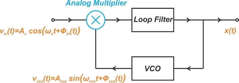
Figure 5. The VCO output exhibits a 90-degree phase shift relative to the incoming FM wave.
In the locked condition, the VCO oscillates precisely at the unmodulated carrier frequency (ωc = ωvco) and the loop sustains a 90-degree phase difference between the input FM wave and the VCO output. Hence, with a cosine input waveform, the VCO output is considered to be a sine wave. Under lock conditions, the feedback mechanism results in:
$$\phi_{vco}(t) ~\approx~ \phi_{in}(t)$$
Equation 2.
Differentiating both sides of the above equation yields:
$$\frac{d}{dt} \phi_{vco}(t) ~\approx~ \frac{d}{dt}\phi_{in}(t)$$
Equation 3.
Since the input is an FM wave, the input angle, ϕin(t), is related to the message signal, m(t), by the integral:
$$\phi_{in}(t) ~=~ 2 \pi k_f \int_{0}^{t} m(\tau) d \tau$$
Equation 4.
where kf is the frequency deviation constant.
A similar equation relates the VCO's angle, ϕvco(t), to its control voltage, x(t):
$$\phi_{vco} (t) ~=~ 2 \pi k_{vco}\int_{0}^{t} x(\alpha) \ d \alpha$$
Equation 5.
where kvco is the frequency sensitivity of the VCO measured in Hz/V.
Substituting Equations 4 and 5 into Equation 3 yields:
$$k_{vco} x(t) ~\approx~ k_{f} m(t) \quad \Rightarrow \quad x(t) ~\approx~ \frac{k_{f}}{k_{vco}}m(t)$$
Equation 6.
It is evident that the VCO's control voltage reproduces the message signal.
Quadrature Detector vs. PLL-Based FM Demodulator
In a previous article, we learned about FM demodulation using a quadrature detector (Figure 6). In a quadrature detector, both the input FM signal and its phase-shifted signal are directed to a phase detector. The output is subsequently processed by a lowpass filter.
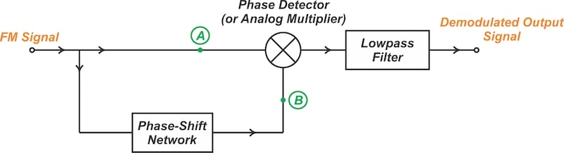
Figure 6. Block diagram of a quadrature detector.
It's noteworthy that the quadrature detector and the PLL exhibit certain similarities in their operation. Both the quadrature detector and the PLL employ a phase detector followed by a lowpass filter.
In a quadrature detector, the phase-shift network produces a nominal 90-degree phase shift at the unmodulated carrier frequency. In the PLL, the feedback arrangement maintains a 90-degree phase difference between the input FM wave and the VCO output. In both the quadrature detector and the PLL, the phase detectors operate on identical signals, comparing the input FM signal to its phase-shifted version.
From a performance viewpoint, however, the PLL can have a lower threshold. This is because the signal produced by the VCO is cleaner than the phase-shifted signal used in the quadrature detector. For that reason, the PLL demodulator is sometimes referred to as the threshold extension demodulator.
Wrapping Up
By incorporating a feedback configuration, the PLL-based FM demodulator allows us to narrow the FM detector's bandwidth. Unlike a slope detector, which uses circuits with a bandwidth equal to or greater than the FM wave, the PLL demodulator's output bandwidth matches the message signal, which is usually much narrower. This reduction in signal bandwidth helps improve the demodulator's noise performance.
This article is Part 5 of a five-part series on FM demodulator circuits. All articles in this series are listed below in order of publication:
- Introduction to Frequency Discriminators for FM Demodulation
- Understanding Slope Detectors for FM Demodulation
- FM-to-AM Conversion Using the Foster-Seeley Discriminator
- Basic Principles and Implementation of the Quadrature FM Demodulator
- FM Demodulation Using a Phase-Locked Loop
All images used courtesy of Steve Arar


I made one of these for a project at university, quite a while ago. There was no maths. I just happened upon the idea that if I could phase lock one of those FM bugs to a radio station then the audio input to the bug would match the radio station’s audio. It worked fine. A friend who was into RF showed me how to make a balanced diode modulator from one of those 2-holed balun cores. I think I added a single transistor preamp, mainly to stop VCO RF leaking out the antenna. Built it up using an air wiring technique soldered between power “rails” that some people said wouldn’t work at that frequency (until I pointed out it has a wavelength of 3m).