Facebook
 Google
 GitHub
 Linkedin
Basic Principles and Implementation of the Quadrature FM Demodulator
Learn how an analog multiplier or AND gate can function as a quadrature detector for FM demodulation.
Earlier articles in this series discussed FM demodulation methods such as the slope detector and the Foster-Seeley discriminator. While these discriminators hold historical importance and are educational to study, they are no longer in use. The quadrature detector, on the other hand, continues to see wide use in FM demodulator ICs. In this article, we'll delve into the operating principles of the quadrature detector and examine both an analog and a digital implementation.
Quadrature FM Detection: The Fundamental Concept
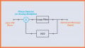
A quadrature detector incorporates a phase-shift network and a phase detector to demodulate FM signals, as illustrated in Figure 1.
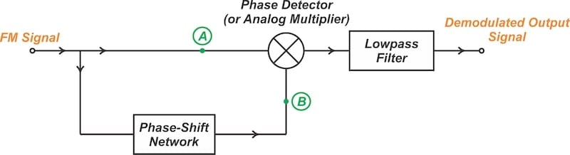
Figure 1. Block diagram of a quadrature detector.
The incoming FM signal is split into two paths. One path sends the signal directly to the phase detector, while the other path sends the signal through a phase-shift network. The network shifts the phase of the incoming FM signal by an amount proportional to its instantaneous frequency. The phase detector compares the signals at nodes A and B, and produces an output that is proportional to the phase difference between them.
To understand the operation of the quadrature detector, note that the phase difference between nodes A and B is proportional to the FM wave's instantaneous frequency, which encodes the message signal. The output voltage of the phase detector therefore varies in accordance with the message signal. In this manner, a frequency-to-amplitude conversion is achieved, and the FM signal is demodulated.
In the next section, we'll mathematically examine a quadrature detector built around an analog multiplier.
Mathematical Analysis of the Analog Quadrature Detector
Analog multiplication is a simple method for implementing a phase detector. Consider an input FM signal described by:
$$s_{FM}(t) ~=~ A_c \sin \big [ 2 \pi f_c t ~+~ 2 \pi k_f \int_{0}^{t} m(\alpha) d \alpha \big ]$$
Equation 1.
This signal is fed into one input of the analog multiplier (node A in Figure 1) and passes through a phase-shift network to reach the other input (node B). The phase-shift network used in a quadrature detector produces a phase shift (Δθ) that can be represented by:
$$\Delta \theta ~=~ \frac{\pi}{2} ~-~ k (\omega-\omega_c) ~=~ \frac{\pi}{2} ~-~ k \Delta \omega$$
Equation 2.
where:
ω is the angular instantaneous frequency
ωc is the unmodulated carrier frequency
k is a constant.
As observed, the network exhibits a nominal 90-degree phase shift at the carrier frequency (when ω = ωc). As the input frequency deviates from ωc, an additional phase shift term proportional to ω – ωc is introduced. Therefore, the typical phase response of the network around the carrier frequency is as shown in Figure 2.

Figure 2. The phase-shift network introduces a phase shift proportional to the input frequency.
By applying Equation 2, the phase-shifted signal at node B can be expressed as:
$$\begin{eqnarray} s_{shifted}(t) &~=~& A_c \sin \big [ 2 \pi f_c t ~+~ 2 \pi k_f \int_{0}^{t} m(\alpha) d \alpha ~+~\frac{\pi}{2} ~-~ k \Delta \omega \big ] \\ &~=~&A_c \cos \big [ 2 \pi f_c t ~+~ 2 \pi k_f \int_{0}^{t} m(\alpha) d \alpha ~-~ k \Delta \omega \big ] \end{eqnarray}$$
Equation 2.
The signals described by Equations 1 and 2 are applied to the analog multiplier, which is followed by the lowpass filter. But what purpose does this setup fulfill?
When a sine function is multiplied by a cosine function, the result includes components at both the sum and difference of their original frequencies. The lowpass filter following the multiplier removes the sum component, leaving only the difference component. Thus, at the output of the lowpass filter, we have:
$$s_{out} ~=~ Lowpass \Big [s_{FM}(t) \times s_{shifted}(t) \Big ] ~=~ \frac{1}{2} A_c^2 \sin (k \Delta \omega)$$
Equation 3.
For Δω < 0.25 radians, the sine function can be approximated by its argument, leading to:
$$s_{out} ~\approx~ \frac{1}{2} A_c^2 \ k \ \Delta \omega$$
Equation 4.
Hence, the amplitude of the output signal is directly proportional to the deviation of the input frequency from the center frequency. In other words, the circuit serves as an FM demodulator.
Quadrature Detector Using an AND Gate
We can also realize the phase detector using an AND gate, which is simpler to implement than an analog multiplier. Hard limiters before the AND gate convert the intermediate-frequency FM signals into square waves. The phase detector produces a series of pulses whose width changes based on the phase shift between the two signals. These pulses are averaged in an RC lowpass filter to reconstruct the original modulating signal.
This concept becomes clearer when we analyze the typical waveforms of the circuit at various input frequencies.
Typical Waveforms at the Carrier Frequency
First, consider the case where the instantaneous frequency (fi) equals the unmodulated carrier frequency (fc). These waveforms are shown in Figure 3.

Figure 3. Typical waveforms when the input frequency equals the carrier frequency.
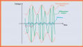
When fi = fc, the phase-shifted signal leads the incoming FM wave by exactly 90 degrees. With a 90-degree phase difference, the two square waves overlap for one quarter of the period. The output of the AND gate is therefore a square wave with a duty cycle of one quarter. The average value of the output is 1/4 of the square wave's amplitude.
Typical Waveforms Below the Carrier Frequency
Next, let's examine the typical waveforms when the input frequency is lower than the carrier frequency. These are illustrated in Figure 4.

Figure 4. Typical waveforms when the input frequency is lower than fc.
In this case, the phase shift between the FM wave and its shifted version is greater than 90 degrees. As a consequence, the overlap between the two signals is less than one quarter of the period.
Averaging these narrower pulses yields a lower output voltage (less than 1/4 of the square wave's amplitude). This reflects the original lower-amplitude modulating signal.
Typical Waveforms Above the Carrier Frequency
Finally, Figure 5 shows the typical waveforms when the input frequency exceeds the carrier frequency.

Figure 5. Typical waveforms when the input frequency is higher than fc.
The phase shift between the FM wave and its shifted version is now less than 90 degrees. As illustrated in the figure, the overlap between the two signals exceeds one quarter of the period, resulting in an average output voltage greater than 1/4 of the square wave's amplitude.
Implementing the Phase-Shift Network
Ideally, the phase-shift network should maintain a constant amplitude response and a linear phase response across the entire spectrum of the FM signal. This is illustrated in Figure 6.

Figure 6. The ideal magnitude (a) and phase (b) response of the phase-shift network.
A phase-shift network can be implemented using either a bandpass filter or a delay line. Figure 7 shows a commonly used phase-shift network based on an RLC circuit.

Figure 7. RLC network for realizing the phase-shift network.
In the above circuit, the input signal is fed through a small capacitor (C1) into a parallel tuned circuit. The resonant frequency of the tuned RLC circuit is almost equal to the carrier frequency of the incoming FM wave. At the carrier frequency (fc), the network can thus be considered as a capacitor in series with a purely resistive component (R).
Due to its capacitive nature, the current through the network leads the input voltage by 90 degrees. This current then flows through the resistor (R), generating an output voltage that leads the input FM wave by 90 degrees.
When the input frequency deviates from fc, the phase shift of the network varies in accordance with it. Determining the exact phase response of the circuit requires establishing the circuit's input-output relationship. Skipping the mathematical derivation, it can be easily shown that the circuit's transfer function is:
$$\frac{V_q}{V_{in}} ~=~ \frac{j \omega RC_1}{1 ~+~ jR \big ( \omega(C~+~C_1) ~-~ \frac{1}{\omega L}\big)}$$
Equation 5.
If we choose the component values so that the carrier frequency satisfies the following relationship:
$$\omega_c ~=~ \frac{1}{\sqrt{L (C_1~+~C)}}$$
Equation 6.
then we can have a constant amplitude and linear phase response around the carrier frequency. Instead of proving this mathematically, we'll improve our understanding of the circuit's behavior by simulating its response for the following example values:
- L = 10 μH
- R = 1.273 kΩ
- C1 = 12.13 pF
- C = 10 pF
The resulting frequency response is shown in Figure 8.

Figure 8. The magnitude (top) and phase (bottom) response of the phase-shift network for some example component values.
For small frequency shifts, the magnitude response is almost constant and the phase response is sufficiently linear to produce acceptable quality audio.
Figure 9 shows the schematic of a quadrature detector employing the RLC phase-shift network of Figure 7.

Figure 9. A quadrature detector with RLC phase-shift network.
Wrapping Up
A quadrature detector incorporates a phase-shift network and a phase detector to demodulate FM signals. This method offers better linearity than the balanced discriminator, making it suitable for constructing high-quality receivers. While FM demodulation techniques like slope detectors and the Foster-Seeley discriminator have fallen out of use, the quadrature detector continues to be relevant and is suitable for implementation in integrated circuits.
This article is Part 4 of a five-part series on FM demodulator circuits. All articles in this series are listed below in order of publication:
- Introduction to Frequency Discriminators for FM Demodulation
- Understanding Slope Detectors for FM Demodulation
- FM-to-AM Conversion Using the Foster-Seeley Discriminator
- Basic Principles and Implementation of the Quadrature FM Demodulator
- FM Demodulation Using a Phase-Locked Loop
All images used courtesy of Steve Arar