Facebook
 Google
 GitHub
 Linkedin
Simplified Circuit-Analysis Techniques for Forward-Conducting Diode Circuits
This article explains two methods that we use to evaluate the currents and voltages that are present in a circuit that includes one or more diodes.
What makes diode circuits so tricky to analyze?
We've discussed the exponential current–voltage relationship in forward-conducting diodes already. In this article, we'll learn how to use this understanding of the current–voltage relationship to facilitate simple diode circuit analysis.
Analyzing Diode Circuits
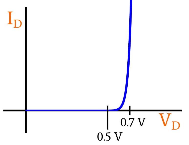
Diodes make circuit analysis more difficult because they have a nonlinear current–voltage characteristic. In other words, a diode doesn’t have a single numerical value that captures the mathematical relationship between current and voltage.
With a resistor, this single numerical value is the resistance, and consequently when we plot a resistor’s relationship between current and voltage, we obtain a straight line. With a typical silicon diode, on the other hand, a plot of the nonlinear I–V relationship looks like the exponential curve shown below.
Method 1: The Diode as a Switch
The most painless (and least accurate) way to analyze diode circuits is to pretend that the diode is a voltage-controlled switch that functions as a perfect one-way valve for electric current. If the voltage across this “switch” is greater than 0 V, current flows freely, without any resistance or voltage drop. If the voltage across the “switch” is less than or equal to 0 V, no current flows.
The first step in this type of analysis is to assume that the diode is conducting or non-conducting. Either assumption will lead to correct results, so just make your best guess. If the diode is assumed to be conducting, keep the diode in the schematic but treat it like a piece of wire. If it is assumed to be non-conducting, replace it with an open circuit.
Now proceed with the analysis, and check for results that make sense. If the voltage across an assumed open circuit is greater than zero, the assumption was wrong—that diode is actually conducting. If the current flowing through a conducting diode is directed from cathode to anode, the assumption was wrong—we’re limiting our analysis to forward-conducting diodes, so current flowing from cathode to anode indicates that the diode is actually non-conducting.
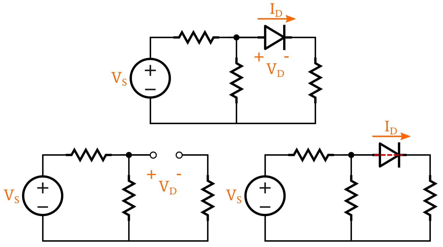
The schematic at the top represents the original circuit. In the bottom left, the diode is assumed to be non-conducting and has been replaced by an open circuit. In the bottom right, the diode is assumed to be conducting and has been replaced by a zero-resistance connection.
This method might seem rather primitive, but it’s actually a handy way to perform a quick preliminary analysis. It’s especially useful when the circuit involves voltages that are quite large relative to typical diode forward voltages, or when a circuit contains multiple diodes and the main concern is determining which ones are conducting.
Method 2: The Constant-Voltage-Drop Approach
When we are using the method described in the preceding section, we are analyzing the circuit as though diodes are ideal, meaning that they function as perfect one-way valves for current. We can make that method much more realistic simply by incorporating an ideal battery that represents the diode’s voltage drop.
The battery becomes an integral part of the overall diode component, as shown in the following diagram.
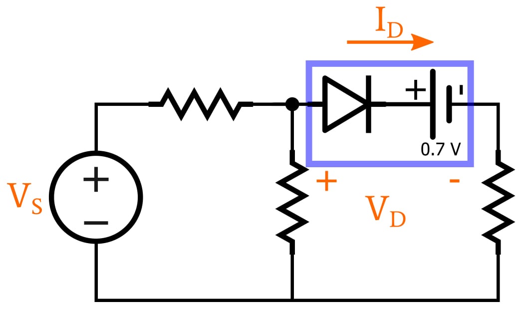
The diode symbol represents an ideal diode, and the battery does two things: it modifies the threshold condition for conduction, and it creates a voltage drop that is present when the diode is conducting.
Since the voltage of an ideal battery is fixed and constant, this analysis technique corresponds to a simplified diode model consisting of two discrete states: If the anode-to-cathode voltage across the diode is less than 0.7 V, the diode is off and functions as an open circuit; if the voltage is greater than or equal to 0.7 V, the diode conducts with zero resistance but produces a voltage drop of 0.7 V. (You don’t have to use 0.7 V as the constant voltage drop, but this is the standard choice for typical silicon diodes.)
Understanding the Constant-Voltage-Drop Model
If you’re unclear on how this model functions, keep in mind that the battery’s polarity is opposing the direction of forward current flow through the diode. Thus, no current can flow from anode to cathode until the forward voltage exceeds the battery voltage, and this means that the battery creates a threshold condition for diode conduction. Also, note that the battery doesn’t generate spurious current that interferes with our circuit analysis, because the ideal diode doesn’t allow current to flow in the cathode-to-anode direction.
After conduction has begun, the battery voltage becomes a normal voltage drop. Again, let’s consider the polarity of the battery. Imagine a resistor in the battery’s place; we would represent the voltage drop of the resistor by drawing positive polarity on the left and negative polarity on the right, and we know that this orientation indicates a loss of voltage as we move along the current path. The battery has the same polarity orientation, and thus it also represents a loss of voltage, in this case caused by a diode instead of a resistor.
Next: Complex Diode Circuit Analysis Techniques
We’ve now covered the exponential I–V relationship of a diode and two methods of facilitating circuit analysis by replacing this exponential relationship with something more straightforward. In the next article, we’ll discuss analysis techniques that are more complex.