 Facebook
 Google
 GitHub
 Linkedin
Getting Started with the Verilog Hardware Description Language
In this article, we’ll study the basic structure of a Verilog module, look at some examples of using the Verilog “wire” data type and its vector form, and briefly touch on some differences between VHDL and Verilog.
In this article, we’ll study the basic structure of a Verilog module, look at some examples of using the Verilog “wire” data type and its vector form, and briefly touch on some differences between VHDL and Verilog.
Verilog and VHDL are two languages that are commonly used to describe digital circuits. AAC has a series of technical articles discussing the basic concepts of VHDL. This article works as a jumping off point for our series regarding Verilog.
Do I Need Both Verilog and VHDL?
Before starting our discussion, let's address an obvious question: do we really need to know both of these two languages?
Both Verilog and VHDL are powerful tools that can be used to design a complex digital circuit. Although there are some differences between these two HDLs, you’re free to choose either one to master and use. However, I believe that at some point, you’ll benefit from having at least a basic understanding of both languages. Sometimes as designers, we need a sample code segment to get an idea about coding a project. We surf the net for hours and finally find what we need but it makes no sense to us—it’s written in the HDL that’s completely unfamiliar to us. Without having a basic understanding of the language, we may not be able to fully understand the techniques.
Verilog Evolution
Verilog was designed in early 1984 by Gateway Design Automation (about three years after VHDL was initiated by the US Department of Defense). With the DoD's support, VHDL became an IEEE standard in 1987. Verilog didn't make it into the scene until 1995. Today, both VHDL and Verilog are popular HDLs and FPGA design tools usually support both languages.
The word “Verilog” is a portmanteau of the words "verification" and "logic" because the language was first suggested as a simulation and verification tool. Let’s get started with Verilog concepts and syntax.
Example 1
As the first example, let’s write the Verilog code for the circuit depicted in Figure 1.
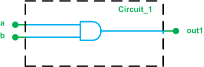
Figure 1. Circuit_1
There are two inputs and one output. The ports are all one bit wide. The functionality of the circuit is to AND the two inputs and put the result on the out1 port.
One possible Verilog description for the Circuit_1 module is:
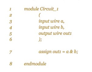
Lines 1 and 8
These two lines use the keywords “module” and “endmodule” to specify that the lines in between (lines 2 to 7) all describe a circuit named “Circuit_1”. This name is arbitrary and allows us to refer to this circuit later.
Lines 2 to 6
These lines specify the interface of “Circuit_1” with its surrounding environment. The input and output ports are described using the keywords “input” and “output”. These keywords are followed by another keyword “wire” and then the name of the port (See Figure 1). What does the keyword “wire” specify? “Wire” is a Verilog data type that represents a physical wire in the design. We’ll discuss the Verilog data types in greater detail in a future article but for now, we know that there would be three wires called a, b, and out1 in our module and since these are specified in the port declaration, they correspond to the module interface.
Line 7
This line uses the bitwise AND operator, i.e. &, to describe the functionality of the circuit. The keyword “assign” puts a&b on the output port out1. This type of assignment is called a continuous assignment. It’s called so because the assignment is always active whenever an operand on the right-hand side changes, a&b is evaluated and assigned to out1. We can envision a continuous assignment as a combinational circuit whose output is continuously updated depending on its inputs. In our example, this combinational circuit is a simple AND gate. There are also procedural assignments in Verilog HDL that will be discussed in future articles.
Now, we can use a software package such as Xilinx ISE to verify the above code. You can find a Verilog-based tutorial of this software here (PDF).
Comparing Example 1 with the VHDL Code
Figure 2 below shows the Verilog and VHDL descriptions for the Circuit_1 module.
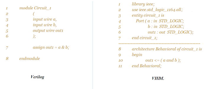
Figure 2. Comparison of Verilog and VHDL descriptions for Circuit_1.
As you can see, we have to include some libraries when coding in VHDL. These libraries give the definition for the data types and operators. Considering the addition of these libraries and the general format of VHDL, we observe that the VHDL code is more verbose. However, this verboseness is not without advantages. For example, the library management feature of VHDL can be helpful when modeling higher-level systems. In future articles, we’ll occasionally discuss the pros and cons of these two HDLs.
Verilog has a Four-Value System
There are four basic values used in most Verilog data types. The wires defined in Listing 1 can take on one of the following values:
- 0: for a logic low or a false condition
- 1: for a logic high or true condition
- z: for the high-impedance state (can be used to describe the output of a tri-state buffer)
- x: for a don’t-care or unknown value (when an input is not initialized or two or more conflicting outputs are connected together).
The VHDL std_logic data type can take on nine different values but its commonly used values are ‘0’, ‘1’, ‘Z’, and ‘-’ (‘-’ denotes a don’t care).
Example 2
As another example, let’s write the Verilog code for the circuit (which we'll label Circuit_2) shown in Figure 3.
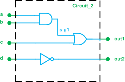
Figure 3. Circuit_2
The following Verilog code describes this circuit:
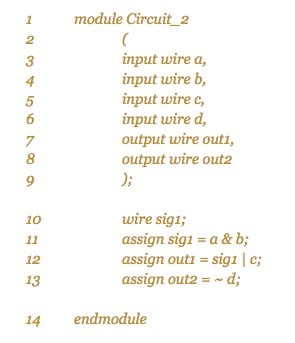
The elements used in the above code are similar to those in Example 1, except that an internal signal is defined in line 10 of the code. The keyword “wire” is used to specify the data type of this connection. As discussed above, the “wire” data type would translate to a physical wire in the design.
The above code also uses some new Verilog bitwise operators: ~ for NOT and | for OR operation. Another useful bitwise operator is ^ for the XOR operation. Figure 4 shows both the Verilog and VHDL descriptions for the Circuit_2 module. Such comparisons can help you see the differences and similarities between these two languages.
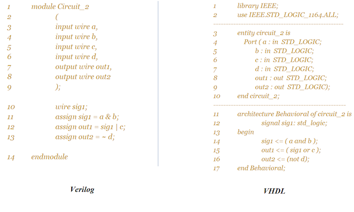
Figure 4. Comparison of Verilog and VHDL descriptions for Circuit_2.
Example 3
For our third and final example, we’ll give the Verilog code for the schematic shown in Figure 5.
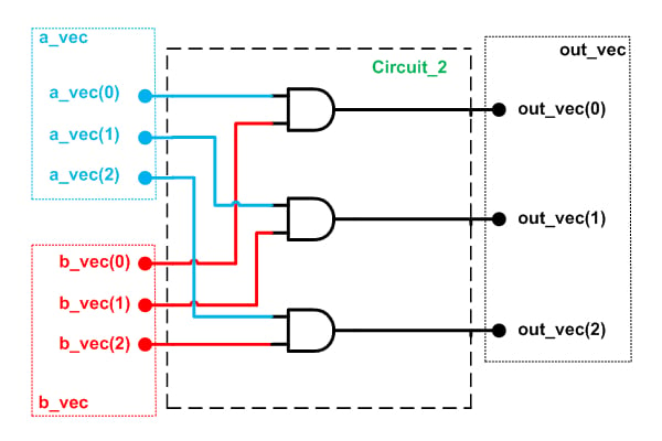
Figure 5. Schematic for example 3.
As you can see, there is a certain relationship between the blue input ports and the red ones: the corresponding inputs are combined with the AND operator. The result is assigned to an output port. In such cases, we can group the signals and treat them as a vector. This makes the code compact and readable.
Using the vector concept in Verilog, we can easily extend the code in Listing 1 to describe the above circuit (See the code in Listing 3 below).
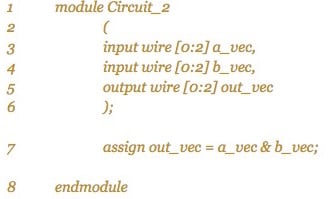
Note that the index range of the vectors can be either ascending ([0:2] as used above) or descending ([2:0]). Although the ascending format is used above, it’s usually less error-prone to use the descending form. This is due to the fact that the descending style matches our perception that the leftmost position of a binary number has the highest index. Note that vectors are also used in VHDL.
Figure 6 below shows an ISE simulation of the code in Listing 3.
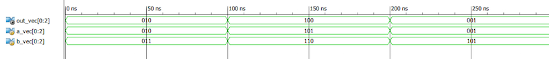
Figure 6. ISE simulation of Example 3's code.
In this article, we discussed that it’s a good idea to learn both VHDL and Verilog, we studied the basic structure of a Verilog module, and we got familiar with the Verilog “wire” data type and its vector form. We also briefly touched on some differences between VHDL and Verilog. The next article in our Verilog series will discuss designing combinational circuits in Verilog.
Related Content


Hi Steve, thank you so much for the clear language and examples that you used. It was very understandable and easy to follow. As a suggestion, I think you should consider putting the link for the next article at the end of the current one. So that it is easier to follow them.