Facebook
 Google
 GitHub
 Linkedin
Implementing Multiplexers with Pass-Transistor Logic
This article discusses the efficient multiplexers that can be created by using MOSFETs in a pass-transistor configuration.
This article discusses the efficient multiplexers that can be created by using MOSFETs in a pass-transistor configuration.
Supporting Information
If you’ve read the previous articles on pass-transistor logic (PTL), you know that this approach to digital design is good and bad. In general the bad outweighs the good, as demonstrated by the preponderance of inverter-based logic in digital ICs of all kinds.
However, we’ve seen that pass-transistor logic really can provide a significant reduction in transistor count, and when it comes to multiplexers, PTL really shines
The Standard CMOS Multiplexer
In a way, it isn’t surprising that PTL leads to efficient multiplexers. Multiplexing is different from the basic Boolean functions. When we’re dealing with AND, OR, NOT, etc., we’re using a logic gate to implement a logic function. That makes sense.
Multiplexing, on the other hand, is more like switching functionality that we might implement using logic gates because they’re readily available and they get the job done. They do indeed get the job done, but not very efficiently—the gate configuration shown below seems rather awkward for a task as simple as selecting between one of two input signals, especially when you consider that each inverter-based AND gate and OR gate requires six transistors.
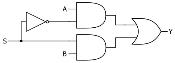
A standard 2-to-1 CMOS multiplexer. When S is logic low, Y equals A; when S is logic high, Y equals B.
The Transmission Gate Multiplexer
In stark contrast to the inverter-based CMOS implementation, a PTL 2-to-1 multiplexer requires only six transistors: two each for two transmission gates, and two for the inverter that provides the complement of the S (select) signal.
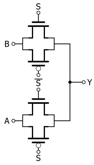
Multiplexing is essentially voltage-controlled switching, and this type of functionality is so closely related to pass-transistor operation that the above circuit needs almost no explanation. The A input signal is connected to an active-low transmission gate, and the B input signal is connected to an active-high transmission gate. When S is low, Y equals A; when S is high, Y equals B.
A PTL 4-to-1 Multiplexer
Pass-transistor multiplexers can be built using transmission gates or the “lone NMOS” type of switch. In terms of pure logic functionality, these are interchangeable—they both pass or block an input signal based on the state of a control signal. However, if you’ve read the previous articles on PTL, you know that the transmission gate provides superior electrical performance.
The 4-to-1 multiplexer discussed in this section uses NMOS switches, mostly because the resulting diagram is more straightforward. Just remember that the NMOS transistor is more or less a placeholder for whatever type of pass/block element is used in the actual circuit. In many cases a transmission gate will be the preferred implementation, or if you want to experiment with these circuits in the lab you could even replace the FETs with a relay or a MEMS switch.
Here is my version of a 4-to-1 PTL multiplexer.
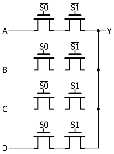
Since there are four input signals, we need a two-bit select signal. These two bits provide four possible binary numbers, and each number corresponds to one of the input signals. The presence (corresponding to logic high) or absence (corresponding to logic low) of an inversion bar above the S signals can be used to translate the diagram into a functional description:
- If S0 = 0 and S1 = 0, Y = A.
- If S0 = 1 and S1 = 0, Y = B.
- If S0 = 0 and S1 = 1, Y = C.
- If S0 = 1 and S1 = 1, Y = D.
Note that this circuit requires an inverter for each S signal. We usually consider the inverter to be a disadvantage associated with the use of transmission gates instead of NMOS switches, but in this case even the NMOS implementation needs inverters because the purpose of the multiplexer is to always pass one of the input signals to the output. In other words, a logic-low select signal is used not only for blocking but also for passing, and a logic-high select signal is used not only for passing but also for blocking. Thus, we need inverters.
Designing Pass-Transistor Multiplexers
The general idea with PTL multiplexers is to configure series-connected switches in such a way that a given combination of S inputs passes one of the input signals to the output node. If there are four inputs, as above, you need two control signals and two series-connected transistors in each input line. If there are eight inputs, you need three control signals and three transistors in each input line. And so forth.
PMOS vs. NMOS
You might be wondering about the possibility of using a combination of PMOS switches and NMOS switches. The 4-to-1 PTL multiplexer needs switches that pass a signal when the controlling voltage is logic low. I achieved this by using an inverted version of the select signal, but if we use PMOS devices for the “active low” switches, we could eliminate the inverters. A PMOS-plus-NMOS solution would look like this:
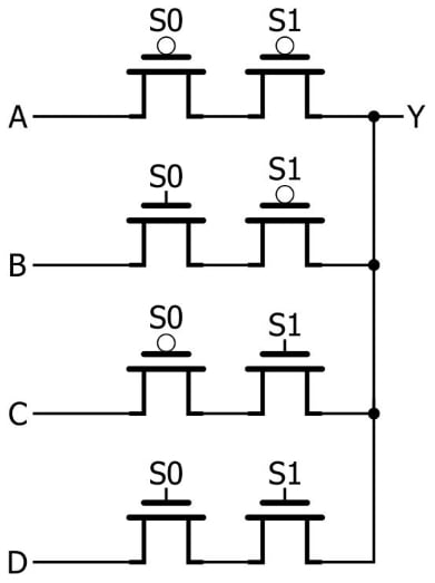
This would be a functional circuit, but I’m confident that the NMOS version would be preferred in real-life applications, despite the fact that the use of PMOS devices reduces the overall transistor count. Electrons have higher mobility than holes, and consequently the electrical performance of an NMOS transistor (which has electrons as the majority charge carriers) is superior to that of a physically equivalent PMOS transistor (which has holes as the majority charge carriers).
This issue is especially relevant to multiplexer designs, because the use of PMOS devices would introduce not only inferior performance but also inconsistent performance: the input-to-output electrical characteristics of the input lines would vary according to how many of each line’s pass/block elements are PMOS transistors.
Conclusion
We’ve explored general concepts and details related to the design of pass-transistor-based multiplexers. In the next article we’ll discuss the use of pass-transistor techniques in the design of sequential logic circuits.