 Facebook
 Google
 GitHub
 Linkedin
Manchester Encoding: What Is It, and Why Use It?
Learn about Manchester encoding, a simple and effective way to improve high-speed or wireless digital communication.
Learn about Manchester encoding, a simple and effective way to improve high-speed or wireless digital communication.
Related Information
You have probably noticed by now that serial digital communication has become rather popular. There are many flavors: Among standard board-level interfaces we have UART, SPI, and I2C. “Digital” communication can also be accomplished by means of analog signals; one example is an RF data link that uses changes in analog amplitude, frequency, or phase to wirelessly transfer binary data. And then there are high-speed differential interfaces, such as serial communication links based on LVDS or USB.
Manchester encoding is a data-modulation technique that can be used in many situations but which is particularly helpful in binary data transfer based on analog, RF, optical, high-speed-digital, or long-distance-digital signals.
Limitations of Standard Digital Communication
Despite the overwhelming advantages of standard digital communication compared to analog signaling, there are some general limitations. One is the issue of synchronization: the receiver must know when exactly to sample the incoming data (note that this synchronization is not necessary in, for example, an analog audio transmission—the demodulated audio signal can be delivered to the speaker without explicit interpretation of data on the receiver side).
Another is the need for DC coupling. Digital data can include long, uninterrupted sequences of ones or zeros, and thus a standard digital signal used to transmit this data will remain at the same voltage for a relatively long period of time. If we attempted to AC-couple this signal using a DC-blocking capacitor, we would run into trouble, as shown in the following LTspice plots.


First the DC offset decays to zero, then everything is fine as long as the signal is transitioning. But when a long sequence of ones or zeros causes the original DC-coupled signal to stop transitioning, the digital signal becomes a constant voltage that is blocked by the capacitor.
Notice that the first plot has an extended logic-low period and the second plot has an extended logic-high period; in both cases, though, the signal decays toward 0 V. Obviously this decay waveform is undesirable in a digital system, but furthermore, the 0 V state is ambiguous—both a long logic high and a long logic low end up at 0 V.
One Solution: AC-Coupling Digital Signals
Manchester encoding offers a remedy to these two limitations. It is a simple digital modulation scheme that does two things: 1) ensures that the signal never remains at logic low or logic high for an extended period of time and 2) converts the data signal into a data-plus-synchronization signal.
Before we go into the details of Manchester encoding, let’s discuss the motivation: Why not just add a separate clock signal for synchronization? And why would we want to AC-couple a digital signal?

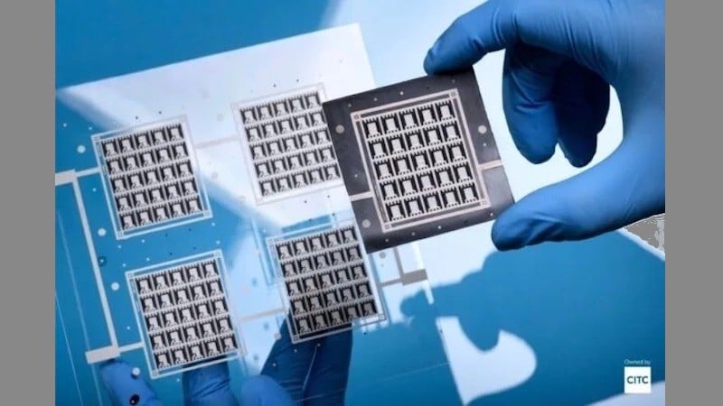
10BASE-T Ethernet uses Manchester encoding.
Clock Avoidance
In many cases, it is perfectly acceptable to use a separate clock signal to achieve synchronization between transmitter and receiver. But sometimes this approach is undesirable, such as when you need to minimize the number of interconnects between parts of a system, or when miniaturization demands the lowest-pin-count microcontroller that can somehow provide the required functionality.
In other situations, a separate clock signal is simply not an option. For example, it would be highly inefficient to include two separate RF transmitters and receivers (i.e., one for data and one for clock) in a complex wireless data link.
If you are familiar with the UART interface, you know that it is possible to use internal timing signals instead of an external clock shared by transmitter and receiver. But this strategy brings significant limitations:
- It is not robust against internal-clock-frequency variations, which become more problematic when the transmitter and receiver are in different environments.
- It lacks flexibility because it requires the Tx and Rx devices to be explicitly preconfigured for the same data rate.
- The receiver generally requires an internal clock frequency that is significantly higher than the data rate, and this could place irksome restrictions on the maximum speed at which data can be transferred.
DC Avoidance
With complex systems, especially those involving high voltages, it is not always easy to ensure that the common-mode voltage of a transmitted signal is compatible with the receiver’s acceptable common-mode range (This is an issue even when using a differential standard such as RS-485). Another concern is fault currents—DC coupling offers no protection against dangerous long-term currents resulting from a short circuit.
Thus, AC coupling is a straightforward way to mitigate the inconveniences and risks associated with common-mode voltages and failure modes.
What is Manchester Encoding?
The fundamental idea behind Manchester encoding is the following: we can use voltage transitions, instead of voltage levels, to represent ones and zeros. Consider the following diagram:

In the upper part of the diagram we have a standard digital interface consisting of a data signal and a clock signal.
In the lower part of the diagram is a Manchester-encoded signal for the same data. Notice how the transitions occur in the middle of the standard-data-signal logic states (in other words, the Manchester transition is aligned with the clock edge that would be used to sample the data). Notice also that a logic-high bit always corresponds to a high-to-low transition, and a logic-low bit always corresponds to a low-to-high transition. (You could also use a low-to-high transition for logic high and a high-to-low transition for logic low; the important thing is that the receiver circuitry knows which format to expect.)
It is immediately clear that the AC-coupling problem is eliminated: every bit requires a transition, and therefore the data signal will never remain at logic low or logic high for an extended period of time. This is evident in the following diagram, which shows a standard digital signal for binary 111111 and a Manchester-encoded signal for the same binary sequence.

The synchronization issue is a little less straightforward because we still need to somehow extract the clock from the signal; nevertheless, we can intuitively see that the regularity of the transitions provides information about when the data signal should be sampled.
The previous diagram also demonstrates a nontrivial disadvantage of Manchester encoding: the data rate is cut in half relative to the bandwidth of the data signal. A Manchester-encoded signal needs a transition for every bit, which means two Manchester logic states are used to convey one standard logic state. Thus, twice as much bandwidth is needed to transfer data at the same rate.
This may not seem like a problem—why not just use a higher-frequency signal? Well, if signal bandwidth is the limiting factor in how quickly data can be moved from transmitter to receiver, and if you already are at the maximum data rate, you can’t increase the signal frequency by a factor of two; instead, you must reduce the data rate by a factor of two.
Conclusion
You now know what Manchester encoding is and why it is beneficial, despite the potentially reduced data rate and the additional circuitry or firmware needed to generate and interpret the Manchester-encoded data. A future article will provide specific implementation details for those who want to explore Manchester’s more practical side.


Outstanding article. Thanks for including the “why” along with the “what” of Manchester. Keep it up!