 Facebook
 Google
 GitHub
 Linkedin
Why Source Shifting Is Important and How to Use It
This article explains the rules associated with the technique of source shifting.
This article explains the rules associated with the technique of source shifting.
Electrical engineering has become an integrated part of our day-to-day life in part due to our dependency (in fact, some may say over-dependency) on various electronic equipment. This has created a huge demand, and of course a huge market, for a vast variety of electronic components. As a result, engineers around the world are forced to design and redesign many things. Some may be as simple as a switch used to light-up a home or while others may be a complex network such as a global positioning system (GPS) used over our tiny mobile-sets.
What is actually meant by ‘design’? Is it just building the essential circuit? No—absolutely no. By "design" we actually mean the different phases involved in bringing a successful product to the market. The major phases for an EE include building, testing, and debugging the circuits, the actual skeletons of every electronic product.
The Need for Circuit Minimization Techniques
The complexity of the circuits designed varies wildly depending on the application for which they are built. Nevertheless, both designers and debuggers need to have an in-depth knowledge on the composition and working of these electrical circuits. In these jobs, the various techniques of network analysis gain prime importance.
In addition to analysis techniques, even circuit minimization techniques become important in the context explained. This is because it is easier to understand a circuit (or anything, for that matter) when it is brought to a reduced form wherein we have a reduced number of components performing the same set of operations.
Source transformation is just such a circuit minimization technique. From the discussion presented in my article on source transformation, it is clear that in order to apply source transformation to voltage sources, you must have an impedance (a resistor, capacitor, inductor, or any combination of these) in series with the voltage source in the circuit. Similarly, in order to transform the current source into a voltage source, the current source should have an impedance (a resistor, capacitor, inductor, or any combination of these) in parallel with it.
Source Shifting
Now, what if we have a circuit which has nothing like described above? Can we never apply source transformation technique to reduce such a circuit? No, nothing of the sort! We still have a small lifeline which manifests itself in the form of source shifting.
By source shifting, we may mean either the shifting of current source or shifting of the voltage source—very similar to that in the case of source transformation.
Shifting of Voltage Source (V-Shift)
Consider the case where we need to apply voltage-to-current source transformation for a network which has a single voltage source connected to a couple of impedances. Figure 1a shows such a node, a, at which the positive terminal of the voltage source, V, is connected to a couple of impedances: Z1 to Z4.
Here we can't transform the voltage source, V, as it has no impedance in series with it. However, we can push this voltage source through the node, a, towards the individual branches of the network. But while doing so, we have to take care that the current distribution through the circuit remains unaffected.
Figure 1b shows the resultant circuit obtained by the push through mechanism of the voltage source. At this instant, we observe that, after V-shift, the voltage source is made to appear at every branch of the electrical network in series with the impedances present in each of them.
In addition, we can see that the polarity of the voltage source remains the same with respect to each of the impedances (i.e., the positive terminal of the voltage source remains connected to the left-side of the impedances in each branch in Figure 1b similar to that as in the case of Figure 1a). As a result, Figures 1a and 1b are treated equivalently except for the fact that we can apply source transformation to Figure 1b while we can't do so to Figure 1a.
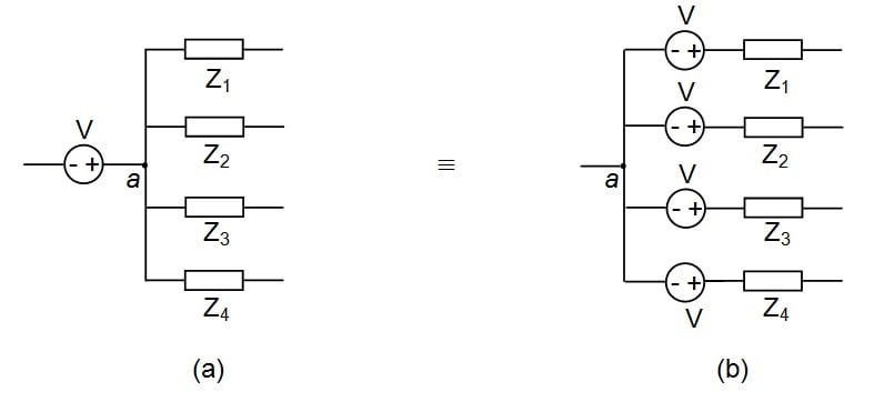
Figure 1
Next, consider another electrical network, like that shown in Figure 2a, where there are a couple of impedances joined at either ends of the voltage source. That is, Z1, Z2, and Z3 are connected to the negative terminal of the voltage source, V, while Z4 and Z5 are connected to its positive terminal.
In such a network, we can see that one may either push or pull the voltage source in order to make the circuit suit the needs of source transformation. However, in either case, the polarity of the voltage source which is being shifted needs to be maintained unaltered so as to ensure same current distribution through the network.
With reference to Figure 2a, this analogy can be explained as follows. The voltage source, V, in Figure 2a can either be (i) pushed through the node, a, towards the individual branches Z4 and Z5 or (ii) pulled through the node, b, towards the individual branches Z1, Z2, and Z3.
Nevertheless, in either case the polarity of the voltage source should be dealt with using extreme care. The networks resulting from such push-pull operation are shown by Figures 2b and 2c, respectively.
.jpg)
Figure 2
Having known that both push and pull are valid, now comes the question of which one to use. The decision is specific to the given circuit and is sometimes subjective (a matter of pure choice). Therefore we can't generalize a best practice here.
Shifting of Current Source (I-Shift)
Shifting of current source within the network is undertaken so as to make the given electrical circuit suitable for current-to-voltage source transformation. That is, I-shift helps us obtain a current source in parallel with a branch which has an impedance in it.
However, even in this case, we have to be cautious about the polarities of the associated current source(s), similar to what we saw in the case of V-Shift. The reason for this is that, while shifting the current source, we have to maintain the same current at all the nodes of the associated network.
This concept can be better understood by considering an example as the one shown in Figure 3a. Here, there is a current source, I, connected between the nodes, a and c, such that current leaves node c and enters into node a.
This circuit can be redrawn as shown in Figure 3b wherein the identical current source is made to exit from node c, enter into node b, exit from node b, and enter into node a.
Here we should note that, even though the current is made to enter node b, it has no effect on the node. This is because an identical amount of current is made to exit from node b. This means that the circuits shown in Figures 3a and 3b are equivalent to each other, except for the fact that one may apply current-to-voltage source transformation readily for the circuit shown in Figure 3b.
.jpg)
Figure 3
Now consider another electrical network as shown in Figure 4a. Here, the current source, I, is connected between the nodes, a and d. In this case, we may shift the current source in two ways: (i) by making it enter-leave the nodes b and c or (ii) by making it enter-leave the nodes h, g, f, and e (taken in order).
The resultant circuits are shown by Figures 4b and 4c respectively and are actually equivalent to each other from an analysis point of view. This is because, in either case, the current, I, leaves the node, a, and enters into d while having no influence on any of the nodes included along its path. Once again, the shifting path undertaken depends on what the situation calls for and is subjective to one’s convenience.
.jpg)
Figure 4
Conclusion
From the discussion presented, it can be concluded that the source shifting process is an important preceding step which aids the technique of source transformation leading to circuit minimization.


Thanks this is very helpfull for me.
Very well-written and easy to understand article. Thanks, this has been very helpful!