Facebook
 Google
 GitHub
 Linkedin
Measuring with Light: New Photometric Front End ICs from Analog Devices
In this article, we’ll take a look at the ADPD10x series, which gives you an example of how a highly integrated IC can simplify your optical applications.
In this article, we’ll take a look at the ADPD10x series, which gives you an example of how a highly integrated IC can simplify your optical applications.
In a previous article, we looked at an ultrasonic controller from Texas Instruments. This IC takes care of details involved in generating, receiving, and processing high-frequency sound signals, with the overall goal being convenient ultrasonic measurements.
In this article, we’ll discuss an IC that could be thought of as the optical equivalent of the TI part. ADI describes it as a photometric front end. Let’s unpack this name: "photometric" refers to measurements involving light intensity and "front end" indicates that the chip provides functionality related to signal generation, signal reception, and whatever signal processing is needed to generate data that can be used by a microcontroller or DSP.

The optical and analog sections of the ADPD10x. Diagram taken from the datasheet.
How Is It Used?
The basic optical functionality here is fairly straightforward: LEDs generate light, photodiodes receive the reflected light. So what exactly does this approach allow you to measure?
The ADPD10x datasheet mentions medical applications, industrial monitoring, and ambient light measurements:
- Pulse oximetry is a convenient way of measuring oxygen saturation; it uses optical signals that pass through blood in the fingertip or some other appropriate body part. Also, page 30 of the datasheet discusses a wrist-based heart-rate measurement device built around the ADPD105 and a green LED:

Diagram taken from the ADPD10x datasheet.
- I don’t have any experience in photometric industrial systems and I’m honestly not sure exactly how this technology might be employed, but I can imagine assembly-line systems that use optical signals to monitor the transparency of glass or the opacity of some manufactured liquid.
- As far as ambient light measurements, I don’t see why you would use an ADPD10x device unless you already have one in your design for some other reason and don’t want to add another component. In all other situations, an ADPD10x seems like overkill for something as straightforward as measuring background illumination levels.
Time Slots
The ADPD10x devices use a “dual time slot” mode of operation. The idea here is that the chip’s functionality—optical transmission, optical reception, signal processing—is contained within one of two time slots. These two time slots (referred to as Time Slot A and Time Slot B) operate sequentially, and furthermore, the time slots work in conjunction with separate data paths, such that Slot A and Slot B can have their own settings.
The following diagram illustrates the sequential time slot arrangement and the way in which optical pulses are contained within each time slot:

Diagram taken from the datasheet.
I assume that this time-slot arrangement has a variety of benefits in the context of typical photometric applications, but I don’t know enough about such applications to make confident assertions. You’re welcome to scroll down and leave a comment if you have any insights.
Interference
Any optical system intended for use in normal human environments needs to be prepared for the effects of interference from other sources of light—unless it is only intended for use during the night, in rural areas, within 48 hours of the new moon.
And this interference is not simply a matter of receiver saturation or a DC offset that can be eliminated by using an AC-coupled circuit. Various situations can lead to optical transients, and fluorescent lights produce non-steady-state interference.
The ADPD10x devices include features that can help you to deal with these complications. The part description states that the chip provides “rejection of signal offset and corruption due to modulated interference caused by ambient light.”
That sounds like a good thing, though honestly I’m not sure exactly what it means (but then again, I didn’t go through all 66 pages of the datasheet). And actually, the word “interference” appears only once in the entire document (meaning the instance in that quote is the only one), so at this point I’m not confident that the datasheet adequately elaborates on this assertion. However, page 43 does mention a “double-sample pair mode” that is useful in situations where the background illumination is “not constant.” That same page also discusses background illumination values and detecting saturation.
The Evaluation Board
The ADPD10x devices are available in two package styles: inconvenient, and exceedingly inconvenient. The first one is what I would call a QFN; ADI calls it an LFCSP. The second is a WLCSP.
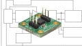
Fortunately, though, there is an evaluation board.

Image courtesy of Analog Devices.
The evaluation board works with GUI software that presumably makes it easy to get the ADPD105 up and running.
I’m still curious about the various ways in which the ADPD10x series might actually be used. If you have any experience in this field, don’t hesitate to share your thoughts in a comment.