 Facebook
 Google
 GitHub
 Linkedin
Multiphase DC-DC Converter Pros and Cons
This article will help you decide when to consider a multiphase approach to step-down, switch-mode voltage regulation.
In a previous article, I introduced the concept of multiphase DC-DC conversion and explained key aspects of multiphase buck regulators. Since single-phase regulator topologies are perfectly adequate for numerous low-power applications, we need to discuss the important question: which designs will benefit most from a multiphase topology?
My objective in this article is to provide enough information on the advantages and disadvantages of multiphase buck regulation to help you identify when the transition to multiphase makes sense.
Rule of Thumb—When to Use Multiphase DC-DC Conversion
I don’t want to give the impression that I’m burying simple guidelines in technical details, so I’ll begin with a rule of thumb for deciding which design projects are candidates for multiphase buck regulation.
The basic trade-off in play here is high-power performance vs. cost and complexity. A multiphase regulator requires more components and more design effort, and this additional investment becomes justifiable as output current approaches the 20 A mark. This threshold, like many thresholds, is somewhat arbitrary, but it’s useful nonetheless. So, if your regulator needs to supply more than 20 A, consider a multiphase solution. You could also consider multiphase if your application requires, say, 15 A of output current and unusually good performance (e.g., low output ripple, enhanced transient response). If you need more than 50 A, definitely consider a multiphase regulator because you’re pretty much at the limit of what a single phase can do.
Disadvantages of Multiphase DC-DC Conversion
As mentioned above, multiphase regulation follows the pattern that seems to characterize most human endeavors: more money + more time + more effort = better results. The dominant disadvantages of choosing a multiphase topology are associated not with electrical behavior but with higher component count and increased design complexity.
A single-phase converter already has the components required for one phase. There’s no escaping the fact that if you add phases, you add components, where phases can share input and output capacitance, but they need their own inductors and field-effect transistors (FETs). Thus, a multiphase topology leads to a regulator circuit that requires higher BOM cost and potentially more board area. Since you have to choose the number of phases, and different designs have different thermal and space constraints, optimizing a multiphase implementation can be tricky and might involve some trial and error.
The increased complexity of a multiphase topology is caused not primarily by the higher component count but by the need for managing the phases (i.e., balancing phase current and enabling or disabling phases in response to load variations). Optimal phase management depends upon complex control schemes, which depend on phase-current-measurement feedback loops. You can read much more about phase-management current measurements in this paper published by Signal Integrity Journal.
Multiphase control is definitely more challenging than single-phase control, but honestly, I don’t see this as a major impediment. We have access to ICs that handle enough of the details to make the overall design process manageable. For example, take a look at this diagram in Figure 1.
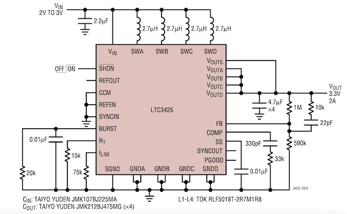
Figure 1. Diagram of the LTC3425. Image used courtesy of Analog Devices
I don’t doubt that some seriously sophisticated control is happening inside this chip, but the circuitry surrounding the chip doesn’t look too bad. Interesting side note: this IC is a multiphase boost converter. Multiphase regulation is more common for step-down applications, but keep in mind that it can be used for step-up applications as well.
Advantages of Multiphase DC-DC Conversion
The fundamental benefit of a multiphase approach is the reduced load current that each phase supplies, but this modification branches out into various desirable effects. Let’s explore the details.
Lower Capacitance Requirements
The interleaved nature of the phase timing in a multiphase architecture reduces the maximum (and RMS) current drawn by the switcher’s input circuitry. This means that input capacitance can be reduced while maintaining equivalent ripple performance.
Something similar occurs on the output side. In the previous article, we looked at a schematic and a timing diagram taken from a research paper about multiphase buck regulation for charging EV batteries. Take a look at this output-current diagram from the same paper (Figure 2).

Figure 2. Example current-output plot. Image used courtesy of Reyes-Portillo et al
In this four-phase topology, each phase must supply one-fourth of the required output current, and the output ripple is consistent from phase to phase. However, as shown in the IO plot, the sum of these currents has a lower ripple because the current variations from individual phases don’t occur simultaneously, resulting in partial cancellation. If the output current ripple is lower, the same output-voltage ripple requirements can be satisfied with less output capacitance.
Transient Response
As mentioned above, a system that is particularly susceptible to load-current transients may be a good candidate for multiphase regulation. As discussed in the previous article, phases are usually activated sequentially, perhaps with some overlap. However, a multiphase controller can activate or deactivate phases simultaneously in response to a sharp increase or decrease in load current. Phases controlled in this way function as though their inductances are in parallel, and since parallel connection reduces equivalent inductance, impedance is reduced, and transient response improves.
Adding and Shedding Phases
The presence of multiple phases allows a switch-mode controller to optimize efficiency by increasing or decreasing the number of active phases. “Shedding” phases refer to the practice of deactivating phases in response to low-load-current conditions. Let’s examine the following diagram, Figure 3, taken from a Master’s thesis (namely, Figure 3.1, p. 19) on advanced phase-shedding techniques.

Figure 3. Example plot showing efficiency vs. load current. Image used courtesy of Anagha Rayachoti
At low load current, maximum efficiency is achieved with one phase, but as current increases, efficiency eventually decreases until the system operates more efficiently with two phases. This pattern continues until maximum efficiency is achieved with all phases active. Thus, even if multiple phases are not strictly necessary because of high load-current requirements, a multiphase approach brings the possibility of improved efficiency, especially in systems that experience large variations in current consumption.
DC-DC Conversion Objectives
The fundamental objective of multiphase DC-DC conversion is to enable higher output current by dividing the task of supplying load current among multiple phases. However, we’ve seen that a multiphase DC-DC regulator confers various other benefits, namely, reduced capacitance requirements, improved transient response, and higher average efficiency over a wide output-current range. If you’ve ever had to consider these effects when deciding between a single-phase and a multiphase solution for a particular project, it would be great to read about your experiences in the comments section below.


Thanks for this article.
I’d love to hear more about the limits of single phase in the “50A+, definitely go multiphase / sync” rule of thumb. Is it simply a rough correlation of the conduction/switching losses of standard packages of transistors and inductors or is there another consideration (closed loop stability, the performance cost of single overlaps with multi so go multi)?
I’ve been considering challenging myself to put together a low voltage high current boost converter (far exceeding 200A) for supercaps. The comment about single phase being able to do only so much intrigued me because I considered that you could always scale up your switching and magnetics footprints.