Facebook
 Google
 GitHub
 Linkedin
A Brief Review of the Tools and Parameters of EMC Testing
While most electromagnetic compatibility (EMC) tests are conducted in specialized laboratories, electrical engineers can still benefit from knowing the basics of EMC testing.
In previous articles, we introduced conducted and radiated electromagnetic compatibility (EMC) tests. Even if they have different purposes, both kinds of tests share some components at their test set-ups.
This article explains the details of some of the tools widely used for these EMC tests. We'll also outline some of the main parameters to take into account when defining an EMC test plan for a specific product.
Tools and Equipment for EMC Testing
Open Area Test Site
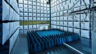
The area of the test set-up must be reflection-free, which means that any object with reflective properties must be removed. This can be accomplished by placing the test setup on an open area test site (OATS)—although, an OATS may be hard to come by depending on your space requirements.
A second option is to simulate an OATS by using a ground plane as the desired reflective surface and using absorbers to prevent all other reflections.

Example of an open area test site. Image used courtesy of Intel
Certain standards—namely, CISPR 25—define some parameters for an OATS, including the material, dimensions of the ground plane, resistance, and separation of the bonding connection points.
Here are the specifics:
- 0.5 mm-thick copper, brass, or galvanized steel
- Maximum resistance of 2.5 mΩ between any two points
- Maximum separation of 0.9 m between consecutive bond straps
Line Impedance Stabilization Networks
Every product to be tested for both radiated and conducted tests will be connected to a power supply. In each different situation, the impedance seen by this power supply will change as a function of frequency. We can use line impedance stabilization networks (LISN) to avoid cumbersome setups and to filter noise coming from the power supply lines.

The frequency response of a LISN. Image used courtesy of Teseq
A LISN presents a uniform impedance and filters external noise. The exact components can vary from one standard to another, but all of them have a schematic similar to the following:

LISN schematic. Image used courtesy of Flex Automotive
BiLog Antennas
Antennas are used in both radiated emissions and susceptibility tests. They can serve as emitters to create intentional interference and receivers to capture all the emissions coming from an electronic product being tested.
EMC tests often utilize BiLog antennas, shown below.

BiLog antenna used for emissions and susceptibility tests. Image used courtesy of EMC Hire
These types of antennas make EMC testing more efficient and convenient because they have a usable frequency range that extends from approximately 30 MHz to a few GHz, such that the same antenna can be used with many different products and test scenarios.
Current Clamps
Current clamps are used to measure and inject circulating current. They act as a transformer; the first winding is the clamp itself, and the second winding is the wiring harness to be measured or subjected to an injected signal.
When placed around a wiring harness, they are used to measure or inject common-mode (CM) currents, which are an important source of radiated emissions.

Current clamps come in different shapes and sizes. Image used courtesy of Solar Electronics Company
Commercial clamps can be opened and closed to snap around a wiring harness. They are usually designed to match 50Ω impedance, the output impedance of most electronic instrumentation. Current clamps are limited by the maximum current that can flow before the core gets saturated and by frequency limits.
EMI Receivers
Electromagnetic interference (EMI) receivers, sometimes referred to as measuring receivers, measure the amplitude of signals captured with antennas or current clamps. EMI receivers can be confused with spectrum analyzers, but there are some differences between the two devices.

EMI receiver. Image used courtesy of Rohde & Schwarz
For example, not all spectrum analyzers can perform a quasi-peak detection—fundamental for CISPR-compliant measurements. In addition, EMI receivers usually offer higher resolution than spectrum analyzers.
Anechoic Chamber
When measuring or generating controlled radio frequency signals, unwanted electromagnetic signals need to be attenuated as much as possible.
Anechoic chambers are covered with materials that absorb or reflect electromagnetic waves. Some laboratories use full anechoic chambers where even the floor is covered with absorbent material. Others use semi-anechoic ones where everything but the floor is covered.

Differences between a fully-anechoic chamber and a semi-anechoic one.

Anechoic chambers are covered by ferrite tiles to absorb electromagnetic waves. Image used courtesy of Lopu
Parameters for an EMC Test Plan
When planning an EMC test campaign, you should know some details before going to the laboratory. EMC laboratories know the test standards they will execute, but all the details regarding the product to be certified need to be defined by the person responsible for the product.
Thus, before going to a laboratory, a test plan must be prepared and delivered. Some relevant parameters worth consideration are listed below.
EMC Emission Limits
The strength of the interference may differ depending on the product type and application (military, consumer, medical, etc.).

Radiated emission limits according to CISPR 11. Image used courtesy of the International Electrotechnical Commission
Limits are defined differently for each standard. Depending on the product type, location, power supply type, and other parameters, maximum emissions levels can vary.
Functioning Modes of a Device Under Test
When testing electronic products, we must simulate a real environment as much as possible so the product performs in a realistic way.
Different functioning modes (sleeping, transmitting, and receiving, for example) must be specified in the EMC test plan. Radiated and conducted tests need to be performed on the device under test (DUT) when the device is working in all of its modes to reveal excessive radiation or possible susceptibilities.
One frequently-used technique relies on software specifically developed for EMC tests that runs cyclically through all the existing functioning modes.
Dwell Time
Dwell time or measurement time is the time spent at each frequency step. This parameter will determine the duration of each test and subsequently, the time and money spent at a certification laboratory.
The determined dwell time depends on the applied standard, which normally specifies a minimum value, and on the DUT functioning modes. It may take a very long time to complete a test if the dwell time is high. Fortunately, we can reduce the duration of the test by using time-domain scanning, a technique that analyzes several bandwidths simultaneously instead of analyzing each one by one.
Conclusion
While most electromagnetic compatibility tests are performed in specialized laboratories, everybody involved in electronic product development can benefit from understanding the basics of EMC tests. Knowledge of the equipment and the parameters of the EMC tests is useful to prepare for pre-compliance tests and successfully pass certification tests.
Related Content