Facebook
 Google
 GitHub
 Linkedin
Sinusoidal Steady-State Analysis
Delve into phasor concepts and transforming a circuit with circuit analysis techniques to solve a given circuit in the frequency domain.
The Sinusoidal Source
A sinusoidal voltage source (dependent or independent) produces a voltage that varies as a sine wave with time. A sinusoidal current source (dependent or independent) produces a current that varies with time. The sinusoidal varying function can be expressed either with the sine function or cosine function. Either works equally as well; both functional forms cannot be used simultaneously. Using the cosine function throughout this article, the sinusoidal varying voltage can be written as:
$$\textit{v}=V_{m}\cos(\omega\textit{t} + \phi )$$ (1.1)
To aid discussion of the parameters of the sinusoidal voltage equation, below is the Fig. 1.1 of the voltage versus time plot
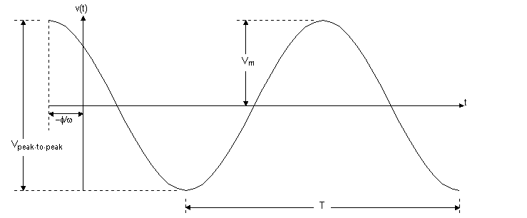
Note that this sinusoidal function above repeats continuously on a regular interval. Such a function of regular intervals, is called periodic. One key parameter is the length of time required for the sinusoidal function to pass through all its possible values. The time required to pass through all possible values is known as the period of the function and is denoted as T. The period of the sinusoidal function is measured in seconds. Taking the reciprocal of T gives the number of cycles per second, or the frequency, of the sine function and is denoted f, where
$$\mathit{f}=\frac{1}{\mathit{T}}$$ (1.2)
A cycle per second is referred to as a hertz, or abbreviated as Hz. In the sinusoidal voltage equation, the coefficient t, contains the value of T or f. Omega ($$\omega $$) represents the angular frequency of the sinusoidal function, where
$$\omega =2\pi \mathit{f}=\frac{2\pi}{\mathit{T}} (\mathrm{radians/second}).$$ (1.3)
This angular frequency equation is based on the fact that the cosine (or sine) function passes through a complete set of values each time its argument, $$\omega \textit{t}$$, passes through $$2\pi $$ rad $$(360^{\circ})$$. Whenever t is an integral multiple of T, the argument $$\omega \textit{t}$$ increases by an integral multiple of $$2\pi $$ rad. The coefficient $$V_{m}$$ gives the maximum amplitude of the sinusoidal voltage. Because cosine is bounded by $$\pm 1$$, $$\pm V_{m}$$ bounds the amplitude. The figure above shows these characteristics.
The angle $$\phi $$ in Eq. 1.1 is known as the phase angle of the sinusoidal voltage. This angle determines the value of the sinusoidal function at t = 0; ergo, it determines the point on the periodic wave at which time is measured from. If the phase angle $$\phi $$ is changed, it shifts the sinusoidal function along the time axis but does not change the amplitude $$(V_{m})$$ or the angular frequency $$(\omega )$$. For example, reducing $$\phi $$ to zero shifts the sinusoidal voltage function shown in Fig. 1.1 to $$\frac{\phi }{\omega }$$ time units to the right, as shown in Fig 1.1. If $$\phi $$ is also positive, the sinusoidal voltage function shifts to the left, whereas if $$\phi $$ is negative, the voltage function shifts to the right. The phase angle, $$\omega \textit{t}$$ and $$\phi $$ must carry the same units, because they are added together in the argument of the sinusoidal function. Normally $$\omega \textit{t}$$ is expressed in radians, but $$\phi $$ is given in degrees, and $$\omega \textit{t}$$ is converted from radians to degrees before the two quantities are added. From trigonometry, the conversion from radians to degrees is given by
$$\mathrm{(number of degrees)}=\frac{180^{\circ}}{\pi }\mathrm{(number of radians)}$$ (1.4)
One more important characteristic of the sinusoidal voltage (or current) is its rms value. This value is defined as the square root of the mean value of the squared function. From Eq. 1.1, the rms value of $$\textit{v}$$ is
$$\sqrt{\int_{t_{0}}^{t_{0}+T}V_{m}^{2}\cos ^{2}(\omega t + \phi )dt}$$ (1.5)
The quantity under the radical sign in Eq. 1.5 reduces to $$\frac{V_{m}^{2}}{2}$$, giving the value of $$\textit{v}$$
$$V_{rms}=\frac{V_{m}}{\sqrt{2}}$$ (1.6)
This value of the sinusoidal voltage depends only on the maximum amplitude of $$\textit{v}$$, namely, $$V_{m}$$. Also, the rms value is not a function of either the frequency or the phase angle.
The Phasor
The phasor is a complex number that carries the amplitude and phase angle information of a sinusoidal function. This idea of a phasor is rooted in Euler's formula:
$$e^{j\theta }=\cos (\theta ) + j\sin (\theta )$$ (1.7)
This equation is important because it gives another way of expressing the cosine and sine functions. The cosine function can be thought of as real part of the exponential function and the sine function as the imaginary part of the exponential function; this gives:
$$\cos (\theta )=\Re\left \{ e^{j\theta } \right \},$$ (1.8)
$$\sin (\theta )=\Im \left \{ e^{j\theta } \right \},$$ (1.9)
Where $$\Re $$ is the "real part of" and $$\Im $$is the "imaginary part of." Using the cosine function in analyzing the sinusoidal steady state as well as the real part of the exponential function, the sinusoidal voltage function is given by:
$$v=V_{m}\cos (\omega t + \phi )$$
$$v=V_{m}\Re \left \{ e^{j(\omega t + \phi )} \right \}$$
$$v=V_{m}\Re \left \{ e^{j\omega t}e^{j\phi } \right \}$$ (1.10)
The coefficient $$V_{m}$$ can be moved inside the argument of the real part of the function without altering the result. Reversing the order of the two exponential functions inside the argument gives:
$$v=\Re \left \{ V_{m}e^{j\phi }e^{j\omega t} \right \}$$ (1.11)
In Eq. 1.11, the quantity $$V_{m}e^{j\phi }$$ is a complex number that holds the amplitude and phase angle of the given sinusoidal function. This complex number is also known as the phasor transform, of the function. Thus, the phasor transform is given by
$$\mathbf{V}=V_{m}e^{j\phi }=P\left \{ V_{m}\cos (\omega t + \phi ) \right \}$$ (1.12)
This phasor transform transfers the sinusoidal function from the time domain to the complex-number domain, or frequency domain. One more thing to add regarding Eq. 1.12 is in order. The periodic occurrenceof the exponential function $$e^{j\phi }$$ has led to an abbreviation. This abbreviation is the angle notation
$$1\angle \phi ^{\circ}=1e^{j\phi }$$ (1.13)
Passive Circuit Elements in the Frequency Domain
First, a relationship must be made between the phasor current and phasor voltage at the terminals of the passive circuit elements. Second, a version of Kirchhoff's laws must be created pertaining to the phasor domain. From Ohm's law, if the current in the resistor varies as a sine wave with time, that is, $$i=I_{m}\cos (\omega t + \phi ) $$ the voltage at the terminals of the resistor, is
$$v=RI_{m}[\cos (\omega t + \theta _{i})],$$ (1.14)
Where $$I_{m}$$ is the maximum amplitude of the current is amperes and $$\theta _{i}$$ is the phase angle of the current. The phasor transform of this voltage is
$$\mathbf{V}=RIe^{j\theta _{i}}=RI\angle \theta _{i}$$ (1.15)
But $$I_{m}\angle \theta _{i}$$ is the phasor representation of the sinusoidal current, so Eq. 1.15 can be written as
$$\textbf{V}=R\textbf{I}$$ (1.16)
Eq. 1.16 is the relationship between phasor voltage and phasor current for a resistor, which states that the phasor voltage at the terminals of a resistor is simply the resistance times the phasor current. Figure 1.1 shows the circuit diagram for a resistor in the frequency domain.
V-I relationship for an Inductor
The relationship between the phasor current and phasor coltage at the terminals of an inductor can be derived by assuming a sinusoidal current and using $$L\frac{di}{dt}$$ to establish the corresponding voltage. Thus, for $$i=I_{m}\cos (\omega t + \theta _{i}),$$ the expression for the phasor representation of the voltage is
$$\textbf{V}=j\omega L\textbf{I}$$ (1.17)
Eq. 1.17 denotes that the phasor voltage at the terminals of an inductor equals $$j\omega L$$ times the phasor current. The voltage and current across the terminals of an Inductor are out of phase by exactly $$90^{\circ}$$. In particular, the voltage leads the current by $$90^{\circ}$$, or, equivalently, the current lags behind the voltage by $$90^{\circ}$$. This can be written as
$$\textbf{V}=\omega LI_{m}\angle (\theta _{i} + 90)^{\circ} $$ (1.18)
V-I relationship for a Capacitor
The relationship between the phasor current and phasor voltage at the terminals of a capacitor from the derivation of Eq. 1.17. Note that for a capacitor that
$$i=C\frac{dv}{dt},$$ then
$$\textbf{V}=\frac{1}{\textbf{j}\omega \textbf{C}}\textbf{I}$$ (1.19)
The above equation denotes that the equivalent circuit for the capacitor in the phasor domain. The voltage across the terminals of a capacitor lags behind the current by exactly $$90^{\circ}$$. This relationship is given by
$$\textbf{V}=\frac{I_{m}}{\omega C}\angle (\theta _{i} - 90)^{\circ}$$ (1.20)
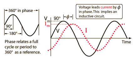
Figure 1.3 shows the phase relationship between the current and voltage at the terminals (\theta _{i}=60^{\circ})

Impedance and Reactance
Concluding this discussion of passive circuit elements in the frequency domain with one more important observation. Comparing Eqs. 1.16, 1.17, and 1.19, are all of the form
$$\textbf{V}=Z\textbf{I}$$ (1.21)
In Eq. 1.21 Z denotes the impedance of the given circuit element. Solving for Z, it can be shown that the impedance is the ratio of a circuit element's voltage phasor to its current phasor. Noting that although impedance is a complex number, it is not a phasor. Recalling, a phasor is a complex number that shows up as the coefficient of $$e^{j\omega t}$$
Impedance in the frequency domain is the quantity analogous to resistance, inductance, and capacitance in the time domain. The imaginary part of the impedance is called reactance. The values of impedance and reactance for each of the component values are summarized in Table 1.1.
| Circuit Element | Impedance | Reactance |
| Resistor | R | -- |
| Inductor | $$j\omega L$$ | $$\omega L$$ |
| Capacitor | $$j(\frac{-1}{\omega C})$$ | $$\frac{-1}{\omega C}$$ |
Solving a circuit in the Frequency Domain
A 400 Hz sinusoidal voltage with a maximum amplitude of 100 V at t=0 is applied across the terminals of an inductor. The maximum amplitude of the steady-state current in the inductor is 20 A.
A) What is the frequency of the inductor current?
The frequency of current in the inductor is also the same as the frequency of the voltage across the inductor terminals. Therefore, the frequency of the inductor current is 400 Hz
B) If the phase angle of the voltage is zero, what is the phase angle of the current?
The phase angle of inductor voltage: $$\phi _{v}=0^{\circ}$$
Since the current through the inductor lags behind the voltage by exactly $$90^{\circ}$$, the phase angle of the currnet is $$\phi _{i}=-90^{\circ}$$
C) What is the inductive reactance of the inductor?
The phasor form of voltage applied across the inductor is, $$\textbf{V}=100\angle 0^{\circ} \mathrm{V}$$
The phasor form of current in the inductor is, $$\textbf{I}=20\angle -90^{\circ}\mathrm{A}$$
Determining the impedance of the inductor:
$$\mathbf{Z_{L}}=\mathbf{\frac{V}{I}}$$
$$=\frac{100\angle 0^{\circ}}{20\angle -90^{\circ}}$$
$$=5\angle 90^{\circ}$$
$$=j5\Omega $$
The Expression for impedance of the inductor is:
$$\mathbf{Z_{L}}=jX_{L}$$
$$=j5\Omega $$
Therefore, the inductive reactance, $$X_{L}$$ of the inductor is $$\mathbf{5\Omega }$$
D) What is the inductance of the inductor in millihenrys?
The expression for impedance of the inductor is:
$$\mathbf{Z_{L}}=jX_{L}$$
$$=j\omega L$$
The expression for the inductor, L:
$$jX_{L}=j\omega L$$
$$L=\frac{X_{L}}{\omega }$$
Substituting $$5\Omega $$ for $$X_{L}$$ and 2513.27 rad/s for $$\omega$$:
$$L=\frac{5}{2513.27}$$
$$=1.99 \mathrm{ mH}$$
Therefore, the inductance of the inductor in millihenrys is $$=1.99 \mathrm{ mH}$$
E) What is the impedance of the inductor?
$$\mathbf{Z_{L}}=j\omega L$$
$$=j(2513.27(1.99*10^{3})$$
$$=j5\Omega $$
Therefore, the impedance of the inductor, $$Z_{L} \mathrm{ is } j5\Omega $$