Facebook
 Google
 GitHub
 Linkedin
Encoding the States of a Finite State Machine in VHDL
This article will review different encoding methods that can be used to implement the states of an FSM.
This article will review different encoding methods that can be used to implement the states of an FSM.
Another AAC article, Implementing a Finite State Machine in VHDL, discusses how to implement a finite state machine (FSM) in VHDL.
This article will review different encoding methods that can be used to implement the states of an FSM. We’ll see that, for a given state diagram, the state encoding method can reduce the power consumption of the FSM or increase its clock frequency.
The State Diagram Representation of an FSM
We can use a state diagram to represent the operation of a finite state machine (FSM). For example, consider the state diagram shown in Figure 1. This FSM has eight states: idle, r1, r2, r3, r4, c, p1, and p2. Also, it has one input, mem, and one output, out1. Based on the diagram, the FSM will choose its next state for the upcoming clock tick.
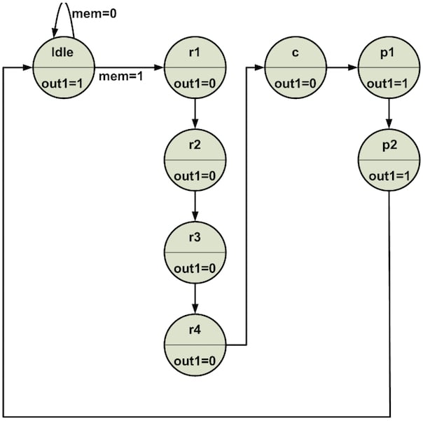
Figure 1
Figure 2 shows the block diagram that can be used to implement the FSM of Figure 1. There are n memory elements, shown inside the dashed box, to store the current state of the system. The box labeled “Logic to Generate the Next State” is a combinational circuit that uses the outputs of the flip-flops (FF) and the system inputs to determine the next state of the system.
This next state will be loaded into the set of FFs at the next clock tick. The box labeled “Logic to Generate the Outputs” receives the current state of the system and generates the output signals. Note that, since the “Logic to Generate the Outputs” is driven only by the state of the system (and not by the inputs), we have a Moore state machine.
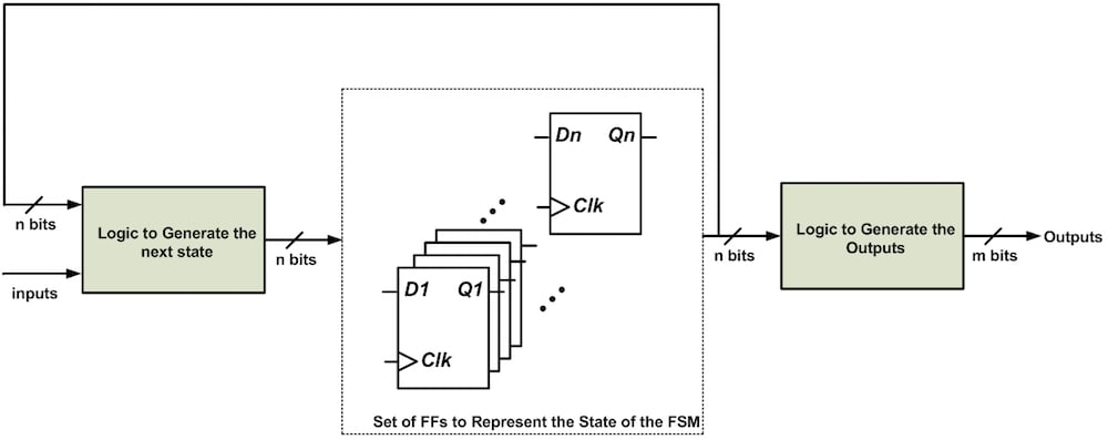
Figure 2
Binary Encoding to Implement an FSM
In Figure 1, we have eight different states. How many flip-flops do we need to represent these eight states?
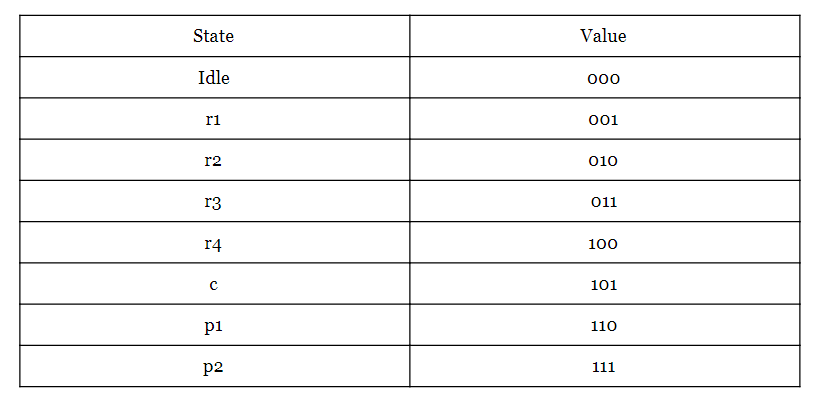
To represent eight states, we need at least three bits. Table 1 shows one possible way of encoding these states; this approach is called binary encoding.
Table 1
This representation leads to the block diagram shown in Figure 3.

Figure 3
Assume that the three-bit string Q3Q2Q1 represents the three bits of Table 1. For example, when the state of the FSM is r3, we have Q3Q2Q1=“011”. Figure 3 depicts three capacitors (Cpar1, Cpar2, and Cpar3). These capacitors serve as lumped-element representations of parasitic capacitance that is present in the circuit. This parasitic capacitance is introduced by the circuit interconnections and by the input stages of the combinational circuits that generate the next state and the outputs.
Let’s examine Figure 1 and Figure 3 more closely. According to the state diagram in Figure 1, for mem=1, each clock tick will make the FSM go from one state to another one. The states are represented by the three flip-flops in Figure 3, and thus with each clock tick, the value of Q3Q2Q1 changes. This means that at least one of the Cpar1/Cpar2/Cpar3 capacitances will need to be charged or discharged. For example, consider the case in which the FSM starts from the state Idle and, after several clock ticks, reaches the state p2. In this case, the capacitor Cpar1 will be charged four times (see Table 1). Similarly, Cpar2 and Cpar3 will be charged two times and one time, respectively.
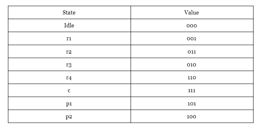
Current is consumed every time a capacitor must be charged. So, part of the power consumed by the circuit of Figure 3 originates from charging the parasitic capacitances that are seen at the output of the FFs. How can we reduce the power consumption of this circuit? One way would be to reduce the number of times that we must charge the parasitic capacitance. Can we rearrange the three-bit assignment of Table 1 so as to reduce the number of transitions at the FF outputs? This is, in fact, possible, and the solution, called Gray encoding, is used in Table 2.
Table 2
Gray Encoding Can Reduce Power Consumption
With the Gray code of Table 2, only one bit changes when moving between adjacent states. Now, when the FSM goes from the state Idle to the state p2, the least significant bit will be charged two times and the second and third bits will be charged only once. (Compare this to the previously required four, two, and one charging events, as discussed above.) Thus, we can use Gray encoding to reduce the power consumption of the FSM.
Gray encoding is great for the FSM in Figure 1 because, for a given state, the next state of the system is known. However, most of the time, we don’t know the next state of the system. For example:
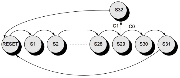
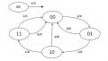
Figure 4. A state diagram that can use the Gray encoding. Image courtesy of Low-Power CMOS Circuits.
In Figure 4, depending on the value of the inputs, the state after S29 can be either S32 or S30. For such cases, we should first determine which path has a higher probability. Then, we can set up our Gray encoding according to the higher-probability path.
Gray Encoding Can Reduce Glitches
As discussed above, Gray encoding can be used to achieve a lower-power design. Another application of this encoding is in protecting asynchronous outputs from glitches. For example, assume that we are using the schematic of Figure 5 to produce the output out1 in the state diagram of Figure 1. This figure assumes that binary encoding is used to represent the states of the FSM.
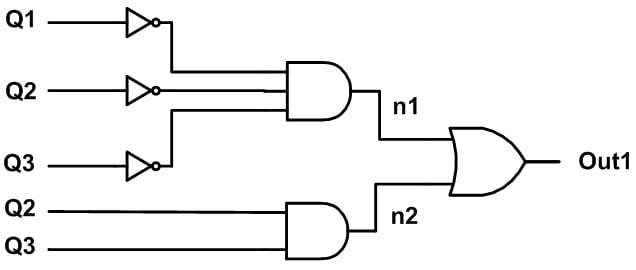
Figure 5
Now, consider the waveforms shown in Figure 6, which correspond to a state change from p2 (111) to idle (000).
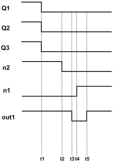
Figure 6
When the system is at p2, out1 is high. At t1, the state changes to Idle. After the time delay of the two-input AND gate, the node n2 will be zero at t2. A little bit later, at t4, the node n1 will go high. Note that the delay of n1 is assumed to be longer than that of n2 because n1 is produced by a three-input AND gate placed after NOT gates.
As shown in Figure 6, the final value of out1 will be one (at t5); however, there is an unnecessary transition from high to low at t3. In circuits such as the one in Figure 5, the unnecessary transition occurs because binary encoding allows multiple bits to change at the same time. With Gray encoding, only one bit changes when moving between adjacent states, and thus glitches are less common.
We have seen that appropriate state assignment can reduce the power consumption of an FSM and make its asynchronous outputs resilient to glitches. There is another state assignment method, namely, one-hot encoding, which can simplify the "Logic to Generate the Outputs" and "Logic to Generate the Next State" blocks in Figure 2. With these two blocks simplified, we can generate the FSM outputs and next state faster. The next section discusses this encoding in more detail.
One-Hot Encoding
Note that in one clock period, the combinational circuits of Figure 2 (i.e., the “Logic to Generate Outputs” and “Logic to Generate the Next state” circuits) should produce their outputs so that the FSM is ready to move to the next state with the upcoming clock tick.
One-hot encoding makes these combinational circuits simpler, which reduces propagation delay, which in turn makes the FSM compatible with higher clock frequencies. The trade-off is that one-hot encoding increases the number of FFs used to store the state of the system. For example, whereas binary and Gray encoding use only three FFs to represent the eight states of Figure 1, one-hot encoding utilizes eight FFs (i.e., one flip-flop per state).
Table 3 shows the one-hot encoding for our eight-state FSM.
Table 3
Why does this make the combinational circuits of the FSM simpler? Because with binary and Gray encoding, we need to use logic gates to “decode” the 3-bit representation into one of the eight states, whereas with one-hot encoding there is nothing to decode—the state corresponds directly to the one bit that is “hot”.
Which State Assignment Is Optimal?
There are some other state encoding options but, in practice, we generally use one of the three encodings discussed above, i.e., binary, Gray, or one-hot.
The question remains: How should we choose the best encoding for a given FSM?
Obtaining optimal state assignment for an FSM is a difficult problem and you can find the theory of this optimization in textbooks such as Synthesis of Finite State Machines: Logic Optimization and Synthesis of Finite State Machines: Functional Optimization. In practice, FPGA synthesis tools can utilize proprietary optimization algorithms to arrive at an efficient implementation of an FSM. If you set the XST (Xilinx Synthesis Technology) fsm_encoding option to “auto”, the software will select the best encoding for each FSM in your design.
As an example, consider the state diagram shown in Figure 7.
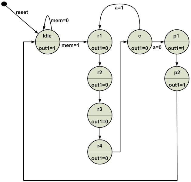
Figure 7
The VHDL description of the FSM in Figure 7 is as follows:
1 library ieee;
2 use ieee.std_logic_1164.all;
3 entity fsm_enco is
4 port(clk, reset: in std_logic;
5 mem, a: in std_logic;
6 out1: out std_logic);
7 end fsm_enco;
8 architecture fsm_enco_arch of fsm_enco is
9 type state_type is (idle, r1, r2, r3, r4, c, p1, p2);
10 signal state_reg, state_next: state_type;
11 begin
12 --set of registers in Figure 1
13 process(clk, reset)
14 begin
15 if reset = '1' then
16 state_reg <= idle;
17 elsif (clk'event and clk='1') then
18 state_reg <= state_next;
19 end if;
20 end process;
21 -- next state logic
22 process (state_reg, mem, a)
23 begin
24 case state_reg is
25 when idle =>
26 if mem='0' then
27 state_next <= idle;
28 else
29 state_next <= r1;
30 end if;
31 when r1 =>
32 state_next <= r2;
33 when r2 =>
34 state_next <= r3;
35 when r3 =>
36 state_next <= r4;
37 when r4 =>
38 state_next <= c;
39 when c =>
40 if a='0' then
41 state_next <= p1;
42 else
43 state_next <= r1;
44 end if;
45 when p1 =>
46 state_next <= p2;
47 when p2 =>
48 state_next <= idle;
49 end case;
50 end process;
51 -- Moore output logic
52 out1 <= '1' when (state_reg = idle or state_reg = p1 or state_reg = p2) else
53 '0';
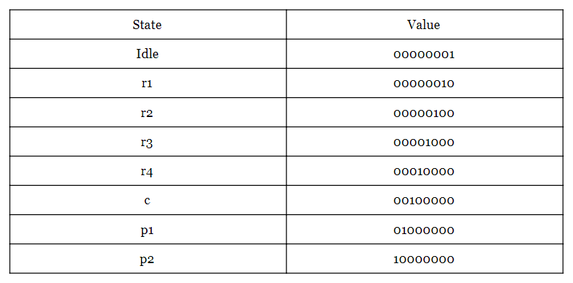
54 end fsm_enco_arch;Using XST to synthesize this code, we obtain the following synthesis log:
=========================================================================
* Advanced HDL Synthesis *
=========================================================================
Analyzing FSM
Optimizing FSM
-------------------
State | Encoding
-------------------
idle | 00000001
r1 | 00000010
r2 | 00000100
r3 | 00001000
r4 | 00010000
c | 00100000
p1 | 01000000
p2 | 10000000
-------------------
=========================================================================
As you can see, XST’s optimization algorithms chose one-hot as the best encoding technique. If you want to choose your encoding method instead of relying on the synthesizer, you can do this via the fsm_encoding option.
Summary
- With the Gray code, only one bit changes when moving between adjacent states. As a result, this encoding technique can reduce the power consumption of an FSM. Moreover, the Gray encoding makes the asynchronous outputs of an FSM resilient to glitches.
- One-hot encoding simplifies the "Logic to Generate the Outputs" and "Logic to Generate the Next State" blocks in Figure 2. With these two blocks simplified, we can generate the FSM outputs and next state faster.
- Obtaining optimal state assignment for an FSM is a difficult problem but, in practice, we can use FPGA synthesis tools with proprietary optimization algorithms to arrive at an efficient implementation of an FSM.
- If you set the XST fsm_encoding option to “auto”, the software will select the best encoding for each FSM in your design.
To see a complete list of my articles, please visit this page.