 Facebook
 Google
 GitHub
 Linkedin
The Initial State of Finite State Machines and the Memory Debate
This article discusses the use of finite state machines (or FSMs) in design, including the initial state and the way memory configuration affects FPGA design.
Encoding of States
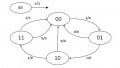
The previous example we covered in the last article didn’t start from scratch: The values of the states were already assigned. It turns out that when you design a state machine, you get to choose which values to assign to each state, and more importantly, how to encode your states.
There are several encodings for state machines, the most popular being binary, Gray, and one-hot encoding. Choosing which encoding to use is a difficult task for a human. That’s why you’re better off letting the compiler choose this for you. We'll talk more about comparing these encodings in my next article.
FSMs in Design
You may now design Mealy and Moore state machines using the technique described above, and once you get the hang of it, it’s all fun and games.
But, aside from school projects, how often will you really need a state machine with an arbitrary behavior like the one we just designed? Almost always! It may not be evident at first, but you may take a top-down approach to describe your system as a sequence of states. This sequence can be drawn as a state diagram, or written down as a state table. Once you get that representation, you’re free to write your HDL code.
Notice that you may or may not end up using output variables like y in our example, and that’s fine because a lot of state machines simply dictate the behavior of the system, and this behavior can be written in the dedicated state cases.
What about the initial state?
Setting up an initial state has been a tricky challenge since the time of traditional logic integrated circuits (think 74LSXX TTL and 40XX CMOS chips). Back then you relied on the Preset and Clear inputs of your flip flops, which were tied to some Power-On Reset signal so that the desired initial state was always set upon power-up.
Now, with FPGAs, there’s a debate on whether or not you should use a reset input signal in your systems to act as such Power-On Reset signal. Our Verilog example with a reset input would look like this:
module MyFSM(
input clk,
input reset,
input x,
output y);
reg [1:0] state;
assign y = state[1]&state[0]&x;
always @ (negedge clk)
if (reset)
state <= 2’b00; // ...or the initial state you want.
else case (state)
2'b00: state <= x?2'b01:2'b00;
2'b01: state <= x?2'b10:2'b00;
2'b10: state <= x?2'b11:2'b00;
2'b11: state <= 2'b00;
endcase
endmodule
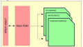
The debate arises because of the fact that most (but not all) FPGAs implement their configuration memory as static RAM (better known as SRAM), which is volatile, and an external nonvolatile memory device is used to copy the configuration into the FPGA at power-on in a boot-up procedure. This boot-up procedure usually enables Verilog initial blocks to be synthesizable!
What this means is that you may not need a reset input signal to initialize your variables when you have a means of initialization in the language. Working with the original Verilog example, it only takes one additional line of code:
initial state <= 2’b00; //
...or the initial state you want.
However, not all FPGAs implement their internal configuration memory as an SRAM. Some FPGAs (like the Lattice MachXO2 family) have an internal nonvolatile configuration memory, so there's no need to boot anything up, making initial blocks unavailable for synthesis, and only valid for initializing test bench modules.
The main reason for initial blocks to be, in general, not synthesizable is that Verilog is intended for many target technologies, including ASIC (which has no boot-up sequence.) At any rate, you should always consider following your FPGA manufacturer’s recommendations about using a reset input or not, or at least find a good reason if you decide to deviate.
FSMs in Soft Processors
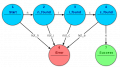
As you may know, the control logic of all CPUs has a state machine somewhere. The states may have descriptive names like Fetch, Decode, Execute, and Write Back, or they may simply be regarded as cycles of execution like cycle 1, cycle 2, and so on. The point is that a CPU core is a surprisingly easy-to-implement application of FSMs in Verilog.
If you’d like to see an implementation of a Soft Processor in Verilog using the techniques described in this article, take a look at Jimmy, an 8-bit soft processor I designed for teaching computer architecture.
Writing an FSM in Verilog may seem intimidating at first, but if you let the synthesis tools help you by entering your code as a case statement, you’ll get your application up and running in a breeze.
In a follow-up article, we’ll explore the differences in the produced hardware when using different encodings in a state machine, with different development tools.


I typically have a reset on all my state machines for one simple reason—it may be necessary to return the design to an initial state without power cycling the device. Whether it’s the ability to perform a soft-reset internally or on command of an external device, or simply to respond to an error condition, many designs require resets for other than power cycling conditions. Should you decide later that you don’t need that type of reset, you can optimize the entire reset network away with one line of code to set the reset signal to a constant non-asserted state. But if you don’t include the reset logic and then discover that you need it, you need to rewrite a lot of RTL code.