Facebook
 Google
 GitHub
 Linkedin
Creating Finite State Machines in Verilog
This article describes the basics of finite state machines and shows a practical way of implementing them in the Verilog Hardware Description Language.
Finite state machines, or FSMs for short, are one of the most ubiquitous models of operation in both hardware and software systems. Virtually every useful digital system can be defined as a finite state machine, so it’s a good idea to learn as much as possible about this useful system pattern.
Finite State Machines in Digital Circuits
A finite state machine is described in many ways, but the two most popular are state diagrams and state tables. An example of both representations is shown in Figure 1.
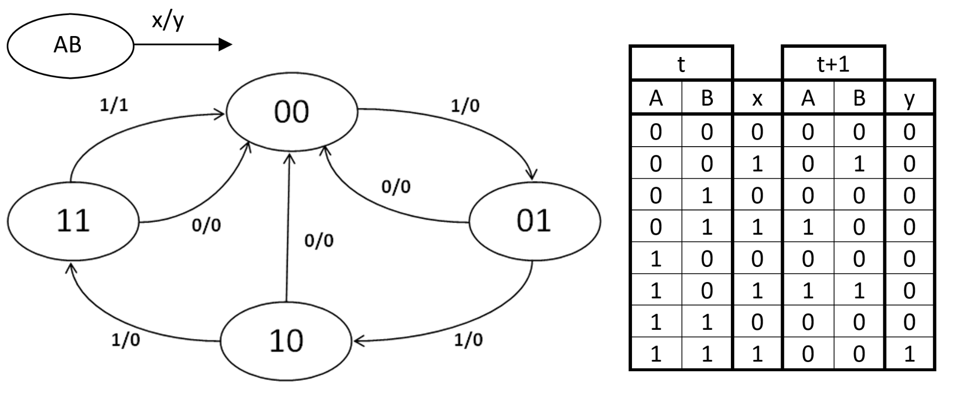
Figure 1. An FSM shown as a state diagram, and as a state table. The legend at the top left shows the state variables A and B, as well as the input x and output y.
Notice that this FSM has an input signal x and an output signal y, which makes it a Mealy state machine. This FSM can be implemented by the traditional method taught in digital design courses, which goes around producing the stimulus logic for the flip flops that implement the state variables. This logic is designed with the excitation table of the selected type of flip flop, namely SR, D, JK, or T.
When we apply this technique to the FSM in Figure 1, we get some version of the following implementation.
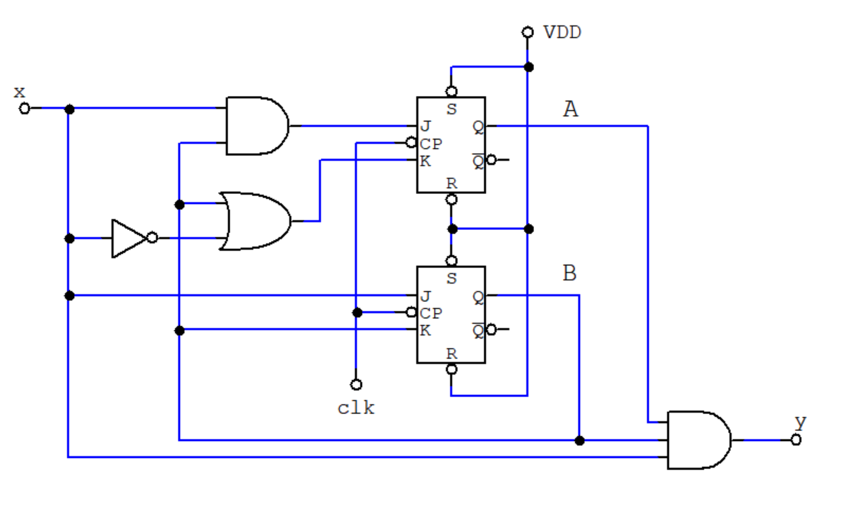
Figure 2. An implementation of the example FSM using JK flip flops.
For more about state machines, you may want to read the article Implementing a Finite State Machine in VHDL by David Williams.
How Verilog Can Help
So, what’s the way to go if you want to implement a state machine like the one in Figure 1 in Verilog? At which point in the design process should Verilog take over?
While it is possible to design the whole system by hand all the way to the schematic diagram in Figure 2 and then write its code in Verilog, that’s not the most popular approach to solving the problem. An even worse approach would be to describe every gate in the schematic, including the gates that make up the flip flops! If you describe everything at the gate level, your system may somehow work, but that leaves no room for the compiler to optimize your design to comply with your real needs, which probably are more focused on timing and power, rather than just correctness.
Remember: The reason for using a hardware description language is to take advantage of the synthesis compiler you’ll use, and like any compiler, the more freedom you give to it, the better chance you’ll have of producing an optimal implementation.
So a clever starting point is the state table. You’ll simply have to instruct Verilog what the machine is supposed to do at each state, not which gates or flip flops to use.
An excellent construct for a state machine in Verilog is the Case statement. The body of each case should examine the state variable and its desired behavior. The following piece of code shows this structure.
case (state)
STATE_0: // Code for State 0
STATE_1: // Code for State 1
// ...
STATE_N: // Code for State N
endcase
So going through with our example, here’s an implementation of the state machine shown in Figure 1. Notice that the output y is a combinational function.
module MyFSM(
input clk,
input x,
output y);
reg [1:0] state;
assign y = state[1] & state[0] & x;
always @ (negedge clk)
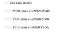
case (state)
2'b00: state <= x?2'b01:2'b00;
2'b01: state <= x?2'b10:2'b00;
2'b10: state <= x?2'b11:2'b00;
2'b11: state <= 2'b00;
endcase
endmodule
Next: FSMs in Soft Processors
In the next article, we'll talk about how we implement FSMs in designs such as soft processors and about the initial state (which can be tricky).