Facebook
 Google
 GitHub
 Linkedin
The Packet Concept: High-Level Synchronization for Data Links
Learn about (for lack of a better term) packetization, a technique that facilitates robust data transfer in optical, RF, and long-distance-digital communication systems.
Learn about (for lack of a better term) packetization, a technique that facilitates robust data transfer in optical, RF, and long-distance-digital communication systems.
Bit-Level vs. High-Level
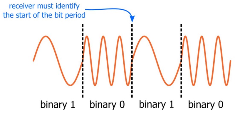
Successful transfer of binary data requires some method of synchronization between transmitter and receiver. Perhaps the more familiar type of synchronization is what I will call bit-level synchronization. This refers to the fact that the receiver cannot correctly interpret digital data if it does not know when to sample the incoming signal.
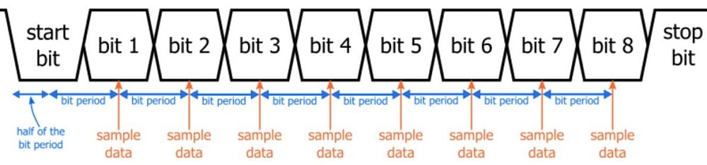
Bit-level synchronization is often achieved by means of a shared external clock signal. In the case of a UART interface, two separate internal clocks are used to achieve bit-level synchronization.
However, there is another type of synchronization that is equally critical but not always as obvious. I will refer to this as high-level synchronization—a term that is sufficiently vague to cover the various specific data-transfer situations that I have in mind.
Ones and Zeros vs. Data
Bit-level synchronization ensures that the receiver reliably interprets each transmitted zero or one as an individual zero or one. But we rarely (if ever) are dealing with a digital communication interface in which the receiver accepts a “stream of consciousness” sequence of ones and zeros that can begin and end at any time without compromising the functionality of the system.
Rather, binary data is organized into coherent groups, and successful data transfer requires that the receiver determine both the individual binary values and the original organization of this binary data. A standard way to facilitate this organized transmission of data—in other words, a standard way to achieve high-level synchronization—is the use of packets.
Packets, Packets Everywhere
Don’t take my word for it; let the devices and professional interface protocols speak for themselves. USB, TCP/IP, integrated-circuit RF transceivers, CAN bus, Wi-Fi . . . they all use packetized data transfer.
The packet concept is a straightforward and intuitive approach to achieving high-level synchronization, but it’s not always necessary. I think that the general idea here will become more clear if we first discuss situations in which high-level synchronization is achieved without packetization.
The Alternative
If you have used SPI, you know how to transfer organized data without using packets. SPI has an additional signal, known as slave-select or chip-select. The receiving device knows that the first bit following the active edge of the chip-select signal is the first bit of a coherent group of ones and zeros. All the following bits are organized into individual bytes, fields, status bits, etc. based on the established protocol.

My point here is that an additional high-level synchronization signal can eliminate the need for full-fledged packetization. But an additional signal is often a non-option: RF, optical, and long-distance wired systems are generally expected to incorporate all the necessary synchronization into one transmitted signal.
Anatomy of a Packet
I hesitate to make specific statements about a technique that can be adapted to such a wide variety of applications; nevertheless, I think it is fair to say that the essential components of a packet are the preamble (aka training sequence), the payload, and the checksum.

Preamble
Let’s say you have a 100-byte packet. Each byte is interpreted in a predefined way—e.g., a status byte, a mode-select byte, the first byte in a 32-bit sensor value. Now imagine that the receiver does not recognize the presence of transmitted data until the second bit; in other words, the first bit is skipped. The result? All 100 bytes are lost, because every received byte will be composed of the last 7 bits of one byte and the first bit of the next byte. This example demonstrates the importance of an effective preamble.
The preamble gives the receiver the time and information needed to make all necessary preparations for correctly interpreting the incoming data.
- Bit-level synchronization must occur during the preamble. As an example, an RF data link might use binary 10101010 as a preamble because the repeated transitions help the receiver to determine the beginning of the modulated bit time.
- If a receiver relies upon automatic gain control (AGC), the beginning of the packet might be unusable because it takes time for the AGC circuit to find the proper gain. The preamble ensures that the AGC can settle before the payload arrives.
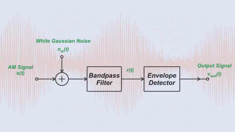
- We have to keep in mind that it is not always easy for the receiver to know whether it is interpreting signal or noise. An RF link operating near its maximum range might result in a rather puny (and/or noisy) demodulated waveform, and then the receiver must somehow recognize that the noise—which it has perhaps been processing all along, in case the noise is actually signal—has been replaced by a valid transmission. When every single packet begins with the exact same sequence of bits, the receiver can safely ignore all the noise bits, which will generally be random and therefore very unlikely to match the preamble.
Payload
The payload is the actual data that the transmitter wants to send to the receiver. It is a series of bits that must be interpreted by the receiver according to the established packet structure.
A related issue that I’ll discuss in this section is packet length. How many payload bytes should be included in one packet? The optimal number varies according to the characteristics of the system. Here are some factors to consider:
- Do you expect frequent bit errors? If so, a shorter packet length is preferable, because just one flipped bit will cause a checksum failure, and a checksum failure means that the entire packet will be discarded.
- Are you trying to maximize your data rate? If so, you want longer packets, because each packet introduces overhead bits that decrease the average rate at which meaningful (i.e., payload) data is transferred.
- Does your receiving device have limited memory? It seems to me that you would usually want the receiver to be able to store an entire packet. Also, if you’re working with a software-defined radio, you might prefer packets that are short enough to allow a digitized baseband waveform for an entire packet to be stored in memory; this makes it possible for you to use a processor that is not powerful enough to decode the baseband signal in real time.
Checksum
Obviously, we don’t design a data link for the purpose of transferring erroneous data. But errors are an unavoidable reality of digital communication, so we need something that will help us to discard data that has been corrupted during transmission. The checksum is a byte (for shorter packets) or a sequence of bytes (for longer packets) that allows the receiver to detect errors in the received data.
A widely used and highly effective error-detection mechanism is the cyclic redundancy check (CRC).
Conclusion
Even a basic UART interface can benefit from the techniques involved in packetized data transfer, and you will definitely need to think about packetization for ambitious projects such as a custom RF data link. Just remember, packetization is not only for the prestigious individuals who design protocols like USB and IEEE 802.11—rather, it is a straightforward and versatile concept that would be a valuable addition to many digital communication systems.
Related Content