 Facebook
 Google
 GitHub
 Linkedin
Transferring LTspice Schematics to QSPICE
In this article, we'll walk through the process of moving an LTspice circuit into QSPICE and learn some QSPICE schematic techniques.
The typical LTspice user already has a collection—maybe even a massive collection—of schematics. Redrawing all these schematics from scratch is about the last thing any potential QSPICE user wants to do. Instead, the goal should be to move circuits from LTspice into QSPICE as easily and efficiently as possible.
Unfortunately for our goals, QSPICE doesn’t include any form of LTspice import functionality. I haven’t found an authoritative explanation for this from either Qorvo or Mike Engelhardt, but it’s reasonable to assume that contractual issues and IP protection are involved.
As forum discussions indicate, this is a serious pain point for QSPICE users, some of whom may attempt to write a third-party LTspice-to-QSPICE schematic converter. Software of that nature would be a boon for the electrical engineering community. It doesn’t currently exist, though, and I’m not holding my breath.
Still, the title of this article is “Transferring LTspice Schematics to QSPICE,” and of course I wouldn’t stoop to false promises. As I’ll demonstrate, there is a way to partially import an LTspice schematic into QSPICE. It’s primitive and inefficient, but probably better than nothing.
In this article, the second in my series on QSPICE for LTspice users, we’ll take the LTspice blinker circuit we created in the first article and turn it into a working QSPICE schematic. For convenience, the LTspice schematic is reproduced in Figure 1.

Figure 1. [Click to enlarge] A two-transistor LED blinker circuit created in LTspice.
We’ll import as much of this circuit as possible using the procedure I mentioned above. After that, we’ll have to redraw the rest. As we do so, we’ll discuss some details of creating schematics in QSPICE.
Importing from LTspice
The first thing you’ll need to do is open the “Tools” menu in LTspice and click “Export Netlist.” Next, open QSPICE and click on File → Open, then select “Netlist Files” in the file-type dropdown and open the netlist you just generated in LTspice. Once you’ve opened the netlist file, select the relevant lines of text as shown in Figure 2. Then, copy them to the clipboard.

Figure 2. The LTspice netlist file for the blinker circuit in Figure 1.
Next, select File → New → New Schematic. This step is illustrated in Figure 3.

Figure 3. Creating a new schematic in QSPICE.
Paste the netlist into the resulting blank schematic by pressing Shift+Ctrl+V. The first component (Figure 4) will appear.

Figure 4. Paste the netlist into the newly created schematic by pressing Ctrl+Alt+V.
A single click will place this component on the schematic. You don’t need to hold down Shift+Ctrl+V—instead, just keep clicking to add the other components. This will also place text elements such as simulation commands and .model statements.
When everything has been pasted, you’ll have a jumble of component symbols with net labels. I recommend rotating the components (Ctrl+R) and placing them in the correct position as you paste them in, keeping the LTspice schematic open on one side of your screen as a reference. If you do this, you should end up with something resembling Figure 5.
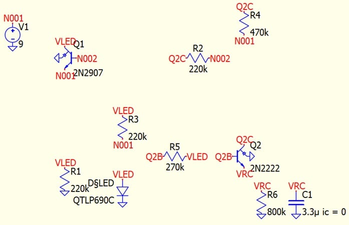
Figure 5. The end result of the LTspice import process.
If you don’t do this, you’ll end up with the mess in Figure 6.

Figure 6. The end result of the LTspice import process if you don’t move the components to the correct positions as you go.
The process above can be broken down into ten steps:
- Export your LTspice schematic as a netlist (Tools → Export Netlist).
- Open QSPICE and select File → Open,
- Select “Netlist Files” from the dropdown menu.
- Open the netlist you exported from LTspice.
- Copy the text you need from the netlist file.
- Select File → New → New Schematic.
- In the blank schematic, use Shift+Ctrl+V to paste the text you copied.
- Click to place the first component on the schematic. Don’t hold down Shift+Ctrl+V.
- Use Ctrl+R to rotate the component into the correct position.
- Repeat steps 8 and 9 for each additional component after the first.
It’s clear from Figure 5 (not to mention Figure 6) that this isn’t a fire-and-forget sort of procedure. The transistors didn’t transfer correctly, and even apart from that there’s still a lot of checking and cleaning up to do before we have a usable schematic. Still, it’s at least better than starting from scratch.
Drawing Schematics in QSPICE
To complete our blinker circuit, we’ll need to use QSPICE’s schematic editing tools. As we’ll see in this section, there are some differences in how we create a schematic in QSPICE versus in LTspice.
Adding Components
One thing you’ll notice is that the main user-interface window has no buttons for wires, components, or node labels. This provides a bit of extra encouragement to use QSPICE’s keyboard shortcuts. I’ve included some useful examples of these in Table 1.
Table 1. Some examples of QSPICE keyboard shortcuts.
| C | Insert capacitor |
| D | Insert diode |
| G | Insert ground symbol (three options are available—keep pressing G) |
| I | Insert current source |
| L | Insert inductor |
| M | Insert MOSFET |
| N | Place net label |
| Q | Insert bipolar junction transistor |
| R | Insert resistor |
| T (or the period key) | Place text |
| V | Insert voltage source |
| W | Start a wire connection |
| Alt+Ctrl+R | Rotate in 45 degree increments |
| F5 | Run the simulation |
Components are also available from the panel on the left side of the QSPICE window (Figure 7).
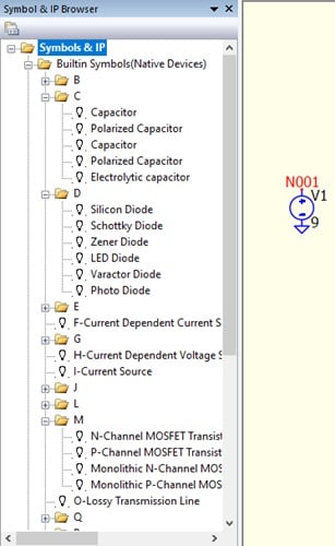
Figure 7. The symbol and IP browser can be found on the left side of the screen.
Adding Component Values and Conditions
Another noticeable difference from LTspice is QSPICE’s emphasis on text rather than dialogue-box windows. For example, I want to set the value of one of the blinker circuit’s capacitors, C2. To enter a capacitance value—3.3 μ, in this case—I just double click on and type it in. Note that a typed “u” will automatically turn into “μ.”
Figure 8 shows C2 before and after its value has been set.
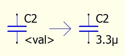
Figure 8. To add a component value, double click and type the value in.
In LTspice, I added an initial condition for the capacitor by using Ctrl+Right-click to open a dialogue. In QSPICE, I’ll just type a .ic statement instead (Figure 9).
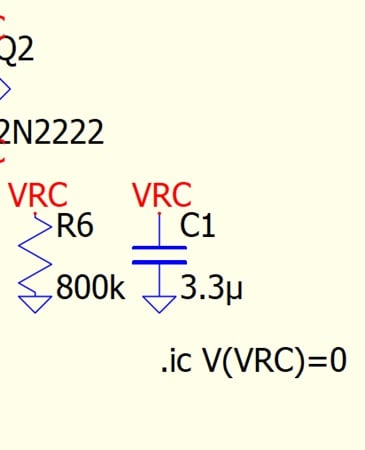
Figure 9. To add an initial condition, just type a .ic statement.
Finally, QSPICE makes the typing method more practical and user-friendly by supplying syntax suggestions as you type. For example, Figure 10 shows the syntax suggestions for a voltage source I want to configure as a sine wave.
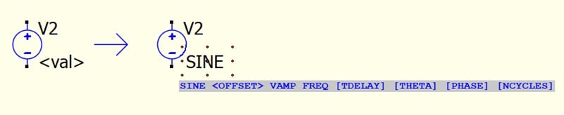
Figure 10. QSPICE provides helpful syntax suggestions when typing.
Choosing Parts From Model Libraries
Say that you’re placing a diode or transistor and want to choose a specific part number from the model library. In LTspice, you would right-click the component and then press the button labeled “Pick New [Component Type]” in the resulting dialogue box. On the surface, QSPICE isn’t much different: you right-click the component, then choose “Selection Guide” from a menu of options (Figure 11).
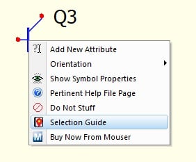
Figure 11. To find a specific part number, right-click the component and open the Selection Guide.
However, as Figure 12 illustrates, you can also just type the part number in (assuming you know it, of course).
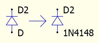
Figure 12. If you know the part number you’re looking for, you can simply type it in.
Jumper Stuffing
Since we’re discussing QSPICE’s schematic editor, I’d be remiss not to mention the “Stuff with Jumper” and “Do Not Stuff” options (Figures 13 and 14, respectively). These are located on the same right-click menu as the Selection Guide.
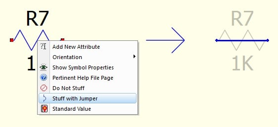
Figure 13. The QSPICE “Stuff with Jumper” option.
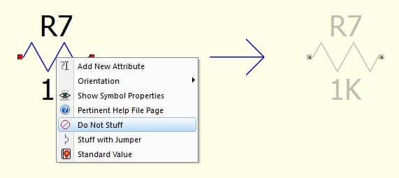
Figure 14. The QSPICE “Do Not Stuff” option.
“Do Not Stuff” and “Stuff with Jumper” are two of my favorite QSPICE schematic features. Testing and refining a simulated circuit sometimes involves eliminating the effect of a component by replacing it with either an open circuit or a short circuit. Via these features, QSPICE allows you to do this quickly and without deleting components that often end up back in the circuit anyway.
The QSPICE LED Blinker
Figure 15 shows the QSPICE version of the LED blinker circuit. Remaking it was a fair amount of work, but the QSPICE schematic editor is pleasant to use (definitely an improvement over LTspice), and we’re talking about free software here, so I’m not inclined to complain.

Figure 15. [Click to enlarge] The QSPICE version of our LTspice LED blinker circuit.
If you compare this circuit to the LTspice schematic in Figure 1, you’ll see a major discrepancy in the LED implementation. As it turns out, the part number I chose for the LED in LTspice isn’t available in QSPICE. There isn’t even a Selection Guide option for LEDs in QSPICE. Furthermore, the parts listed for normal diodes in the Selection Guide aren’t labeled by type (whereas LTspice labels them as “silicon,” “Schottky,” “LED,” and so forth).
Hurdles of this nature have to be expected when you’re transitioning between CAD programs, and it’s good to get in the habit of thinking flexibly and creatively about how to accomplish the simulation objective despite them. In many cases—including this one—a simple workaround saves time and provides enough accuracy for the task at hand.
A perfect LED model isn’t necessary for basic analysis—for now, we just want the circuit to function correctly and to be as consistent as possible with the LTspice version. To imitate the LED’s current-voltage relationship, I replaced the LED with a normal silicon diode in series with a voltage supply.
In the next article, we’ll run our first QSPICE simulations using this circuit. We'll also create another version of the circuit with a different LED implementation. Stay tuned!
This article is Part 2 of a series on QSPICE for LTspice users. Below is a complete list of articles in this series:
- Introduction to QSPICE for LTspice Users
- Transferring LTspice Schematics to QSPICE
- Transferring SPICE Models from LTspice to QSPICE
- Using QSPICE to Understand and Tune an LED Blinker Circuit
All images used courtesy of Robert Keim
Related Content


You could copy the LED model directly from the LTspice “.model QTLP690C D(Is=1e-22 Rs=6 N=1.5 Cjo=50p Xti=100 Iave=160m Vpk=5 mfg=Fairchild type=LED)” And QSPICE will create a symbol model by itself.
I understand this article is about LTspice and QSPICE. My preference is Multisim (there is an online free version) which has far superior schematic simulation capabilities. The paid Multiism version has actual instruments, DMM, oscilloscopes, etc.. Actual instruments are critically important for students, technicians, and engineers. Just my 2 cts.
You said “In LTspice, I added an initial condition for the capacitor by using Ctrl+Right-click to open a dialogue. In QSPICE, I’ll just type a .ic statement instead (Figure 9).”
In QSPICE you can add the initial condition to the capacitor rather than the node VRC, the same as LTspice. Right-click on the capacitor symbol and select Add New Attribute from the context menu. Then type IC=0 into that attribute to set the initial voltage to zero.