 Facebook
 Google
 GitHub
 Linkedin
Understanding and Modeling Piezoelectric Sensors
This article explains some theory behind piezoelectric sensors and presents an equivalent circuit that you can use when you’re designing sensor systems.
This article explains some theory behind piezoelectric sensors and presents an equivalent circuit that you can use when you’re designing sensor systems.
Related Information
Most of us are familiar with the piezoelectric effect because of its role in generating high-precision timing signals. At this very moment, countless electronic devices are being clocked by oscillator circuits built around a quartz crystal. However, quartz is only one of many materials that exhibit piezoelectric behavior, and the functionality of piezoelectric components is not limited to generating clock signals.
The Piezoelectric Effect
I don’t want to dwell on the physics of piezoelectricity; it’s an expansive subject, and the second article listed in the Related Information section (above) provides a good introduction. The bottom line is that the piezoelectric effect is a bridge between the mechanical world and the electrical world.
You can apply all types of physical force to transistors, LEDs, resistors, etc., and in doing so you’re not likely to produce any useful functionality. Piezoelectric devices are the exception. Their electrical behavior responds in a predictable way to mechanical stress, and clever individuals have discovered various ways to incorporate this phenomenon into the world of technology.
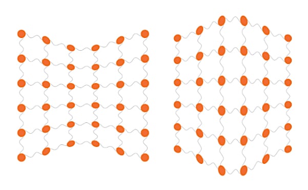
In piezoelectric materials, physical deformation of the crystalline structure, as depicted in this diagram, causes the material to develop an electrical charge.
Piezoelectric Transducers
The word “transducer” usually refers to a device that performs a conversion between the physical realm and the electrical realm. The etymology might help you to remember the meaning: in Latin ducere means “to lead” and trans means “across, beyond, on the other side.” So a transducer is something that leads a signal across the boundary that separates, for example, mechanical variations from electrical variations.
A transducer is not necessarily a sensor. A motor or solenoid is, strictly speaking, a transducer, because it converts an electrical signal into mechanical motion. However, it seems to me that the word “transducer” is used primarily to describe a device that converts a physical quantity into an electrical signal—i.e., a sensor.
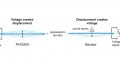
When we consider the nature of the piezoelectric effect, it’s not surprising that a piezoelectric device can function as a force sensor: the use of piezoelectric material allows a transducer to respond in a reliable and predictable way to the mechanical stress caused by an applied force, or by pressure or acceleration (both of which are related to force).
Modeling a Piezoelectric Transducer
Generating Charge
We might think of piezoelectricity as an effect that converts mechanical stress into voltage, but it seems to me that the more precise interpretation is the following: a piezoelectric transducer generates an electric charge in response to mechanical stress. The mathematical relationship between the force applied to the piezoelectric material and the amount of charge generated is governed by a coefficient denoted by d and expressed in coulombs per newton. (One of the names for this value is “piezoelectric charge constant,” but at least three different terms are used; I’ll refer to it as “coefficient” or “piezoelectric coefficient.”) Thus, if a piezoelectric material has a coefficient of 200 picocoulombs per newton, it will generate 200 × 10–12 coulombs of charge in response to an applied force of 1 newton.
Standard circuit diagrams don’t include “charge sources”; the two options are voltage sources and current sources. Fortunately, we can easily create a current source based on the charge generated by a piezoelectric transducer.
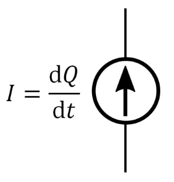
First, we need to recall that electric current (in amperes) is the amount of electric charge (in coulombs) that flows per second through a given portion of a circuit. If we translate this statement into mathematical language, we can say that current is the rate of change—i.e., the derivative—of charge:
$$I=\frac{\text{d}Q}{\text{d}t}$$
Second, we have to recognize that the charge generated by the piezoelectric transducer is not immobile. If the device is connected to a circuit, that charge will move and thus become current. This means that we can model the piezoelectric device using a current source, with the value of the current equal to the derivative of charge.
Incorporating Capacitance
The electrical charge generated by piezoelectric material is introduced into the circuit by means of two electrodes. The resulting physical configuration is something along these lines:
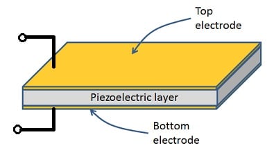
As you can see, the electrodes form a capacitor, and this capacitance becomes an integral part of the device’s equivalent circuit:
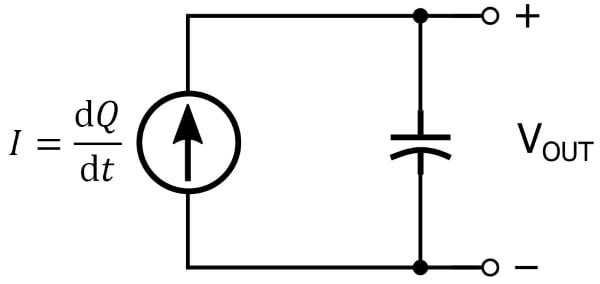
We can calculate the output voltage of the equivalent circuit, labeled VOUT in the diagram, if we recall the relationship between voltage and current in a capacitive circuit. Voltage is equal to the integral of current with respect to time divided by capacitance:
$$V = \frac{1}{C}\int I\ \text{d}t$$
Since the current source in our equivalent circuit is equal to the derivative of charge with respect to time, we have
$$V_{OUT} = \frac{1}{C}\int \frac{\text{d}Q}{\text{d}t}\ \text{d}t=\frac{Q}{C}$$
where C is the value of whatever capacitance is in parallel with the current source (we’ll return to this point in the next article). We saw above that the charge generated by the piezoelectric device is equal to applied force multiplied by the piezoelectric coefficient, and consequently VOUT is proportional to applied force divided by capacitance.
Incorporating Resistance
The current-source-plus-capacitance model of a piezoelectric transducer is adequate for “dynamic” sensing applications—in other words, applications involving physical conditions that are transient in nature or continuously varying. If we want the model to be more accurate as a general representation of piezoelectric functionality, we need to add a parallel resistor:
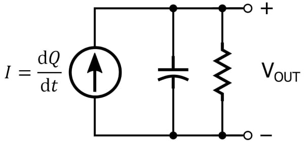
A piezoelectric material generates electric charge in response to mechanical stress, but this charge doesn’t stay around forever. Rather, the material itself functions as a leakage path that causes the charge to gradually diminish. We can account for this behavior by adding a parallel resistor to the equivalent circuit.
Conclusion
We’ve discussed the piezoelectric phenomenon in the context of electronic sensor devices, and we saw that a piezoelectric device can be represented by a current source in parallel with a capacitor or by a current source in parallel with a capacitor and a resistor. In the next article we’ll look at an op-amp topology that provides an effective way to amplify signals from piezoelectric transducers.


Neat breakdown!