 Facebook
 Google
 GitHub
 Linkedin
Piezoelectric Accelerometers: IEPE Sensors vs. Charge Output Sensors
Learn about integrated electronics piezoelectrics (IEPE) sensors, powering them, and how they compare to charge output (non-IEPE) systems.
In a previous article, we discussed the basics of the IEPE accelerometers. In this article, we’ll look at the diagram of a typical power unit that can be used to supply power to an IEPE sensor. We’ll also look at the advantages and limitations of the IEPE type and charge output sensors.
Powering IEPE Sensors—Current Regulating Diodes
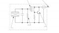
Figure 1 shows the basic diagram of a power unit that can be used with IEPE sensors.

Figure 1. An example block diagram of a power unit with IEPE sensors. Image used courtesy of Dytran
To begin with, a well-regulated DC power source along with a current regulating circuit is required to supply power to the sensor. The DC power source provides typically between 18 to 30 V. As shown in the Figure, current regulation can be achieved through a current regulating diode (CRD). CRDs are diodes that provide a constant current regardless of voltage fluctuations and load resistance changes. A CRD can keep the current constant over a wide range of voltages from less than 1 V to 100 V. The schematic symbol of a CRD is shown below in Figure 2.

Figure 2. A schematic of a CRD.
While a majority of the IEPE sensors can be powered by a 2 to 4 mA current source, currents as large as 20 mA are required in some cases. The maximum current rating of CRDs is typically 4 mA. For larger currents, either several CRDs are used in parallel, or a high capacity constant current circuit is used instead.
Note that a power supply that doesn’t have current limiting functionality should not be used to power an IEPE sensor or the sensor will be immediately destroyed.
The IEPE power units normally have a voltmeter that monitors the sensor bias voltage and informs the user of the system status (a short, open, or normal operating condition). Keep in mind that, with an IEPE sensor, both the output signal and the supply voltage are carried through a two-wire connection.
As shown in Figure 1, many IEPE power units use a coupling capacitor to separate the signal from the DC bias voltage. There are also power units that use DC coupling to avoid reducing the discharge time constant of the system.
Typical IEPE Sensor Systems
As shown in Figure 3, there are two options for powering an IEPE sensor. Some readout instruments have built-in constant current power supplies specifically designed for IEPE sensors. If the readout device doesn’t include an IEPE power supply, a separate power unit should be employed, as shown in the Figure.

Figure 3. Options for powering an IEPE sensor. Image used courtesy of PCB Piezotronics
An example readout device that supports IEPE sensors is shown in Figure 4.

Figure 4. An example readout device and diagram for IEPE sensors. Image used courtesy of NI
Figure 4 shows the NI 9234, which is a four-channel signal acquisition module with software selectable IEPE signal conditioning. As the input circuit diagram shows, the device has a 2 mA constant current power supply and an AC coupling option.
Typical Charge Output (Non-IEPE) Systems
Figure 5 shows a typical measurement system based on a charge output sensor, i.e., a piezoelectric sensor that doesn’t have an integral pre-amplifier.

Figure 5. An example charge output sensor measurement system. Image used courtesy of PCB Piezotronics
In this case, an external charge amplifier is required to convert the charge output of the sensor to a voltage signal. In addition, a well-shielded low-noise coaxial cable should be used to connect the sensor to the charge amplifier. However, a standard coaxial cable can be used between the charge amplifier and the readout instrument.
IEPE Sensors vs. Charge Output Sensors
Most applications today use the IEPE type; however, the charge output sensor has its own advantages. Below, we’ll assess the pros and cons of each method.
Sensor Operating Temperature Ranges
The built-in electronics of an IEPE sensor place an upper limit on the operating temperature range of the system. With standard electronics, the maximum temperature is typically about 125˚C. Using special electronic components can push the upper limit to about 165˚C.
On the other hand, a charge output sensor doesn’t have internal electronics, and its high-temperature limit is set by the Curie temperature of the piezoelectric material. The Curie temperature specifies the temperature above which a material loses its piezoelectric properties. Charge output sensors can operate at temperatures as high as 700˚C.
Furthermore, the IEPE type accelerometers can be popular in the general-purpose testing market, while charge output piezoelectric accelerometers dominate applications where temperatures above about 150˚C are involved.
In addition to the Curie temperature limitation, the insulating resistance of the materials employed in a charge output sensor can also limit the maximum operating temperature of the system. In a previous article, we discussed that the sensor insulation resistance can significantly decrease at high temperatures. We also explained that a small insulation resistance can cause a drift in charge amplifiers.
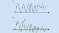
Along with the drift issue, other unexpected and unknown characteristics might be observed when connecting a general-purpose charge amplifier to a sensor with a very small insulation resistance. Figure 6 shows the frequency response of a general-purpose charge amplifier connected to a low-resistance sensor.

Figure 6. A graph of the frequency response of a charge amplifier with a low resistance sensor. Image used courtesy of Endevco
At very low insulation resistance values, the magnitude response of the system exhibits more than 10 dB of peaking at the lower end of the desired frequency range. When working at high temperatures, we need to choose a charge amplifier that can handle very low insulation resistances and maintain a flat frequency response.
Cable Requirements
Charge output sensors require specially treated cables to minimize triboelectric noise. The triboelectric noise refers to the unwanted electric charge produced by rubbing two dissimilar materials together. Flexing or vibration of the cable can cause triboelectric noise. The high impedance output of a non-IEPE sensor can be corrupted by this type of noise and therefore, special low-noise cables are required between the charge output sensor and the charge amplifier. These cables are generally more expensive than standard cables and increase the cost of the non-IEPE system.
Moreover, the high-impedance output of a charge output sensor has limited line driving capability, limiting the cable length between the sensor and charge amplifier to below about 10 meters. On the other hand, standard coaxial cables can be used to transmit the low-impedance output of an IEPE sensor over relatively longer distances without significantly increasing the noise level.
Flexibility in Adjusting Sensor Parameters
With IEPE sensors, the sensor parameters, such as sensitivity and time constant, are fixed at the time of manufacture. We can use external circuits to amplify or attenuate the sensor output but we cannot change the sensitivity or time constant of the sensor. On the other hand, the signal produced by a charge output sensor is processed by an external charge amplifier which can provide us with more flexibility in adjusting parameters such as the system time constant. Special types of charge amplifiers can provide us with very long time constants, extending the low-frequency response of the system.
Additional Features
The IEPE sensors can be operated using relatively cost-effective signal conditioners. Some readout instruments have built-in IEPE power units and can directly connect to an IEPE sensor. If the readout instrument doesn’t have a built-in power unit, we can use an external power unit, as illustrated in Figure 3. On the other hand, with charge output sensors, we need an external charge amplifier. Although laboratory-type charge amplifiers have many helpful features, they are much more expensive than a simple IEPE power unit.
With IEPE sensors, the high impedance signals are placed inside a sealed rugged construction. This makes IEPE sensors less sensitive to harsh conditions such as dirt and humidity.
To see a complete list of my articles, please visit this page.
Related Content


I wrote a very long comment, but only after I clicked submit it told me there was a limit. So this is chopped off and it probably won’t let me post two parts. If you want the full thing, see if you can write me.
I read this and your other article. Both are useful, but what I really want to know is what is available for purchase, where, and how much. You really don’t give a sense of the range of sensitivity. I follow most every kind of accelerometer, vibration sensor, seismometer (usual report velocity, but can operate as an accelerometer), position sensors like LIGO (take second time derivative to operate as an accelerometer).and gravimeter (a gravimeter is just a very sensitive accelerometer. The “best” accelerometers now are superconducting gravimeters, and possibly atom interferometer gravimeters.
You don’t care about that probably. But to be useful to those fields, any “piezo accelerometer” is going to have to meet certain criteria. And your articles just don’t quite provide enough information for me to fill in the rest.
And, without some buyers guide, it is hard to buy parts and build one just to find out what it can do. That is rather like building your own car from a picture. Not impossible, but rather tedious.
The superconducting gravimeter is an accelerometer that can report to an accuracy of about 0.1 nanometer per second squared taking measurements at 1 sample per second. It is capable of tracking the sun moon tidal signal directly. You don’t have any way to attach an image. I have been trying to encourage groups to work together to build gravimeter based gravitational imaging arrays. It is fairly simple once you know how. But depends on high sampling rate (aka “time of flight”) three axis gravimeters. I got into this area because I studied gravitational wave detection back in the 1970’s with the people who founded that and some who went on to build LIGO. I used the superconducting gravimeter array to measure the speed of gravity almost 20 years ago now. And have been trying to find low cost high sensitivity accelerometers since. There are about 10 main kinds of accelerometer. A few groups have built MEMS gravimeters that are sensitive enough to measure the sun moon tidal signal. The advantage of using the sun and moon as references is that most of the signal at a gravimeter station is pure Newtonian vector tidal signal and only about 5% residual of things local to earth. Most of the residual, after taking off the sun moon part is the atmosphere. An array of sensors can image the density variations in the atmosphere, or oceans or inside the earth. A gravimeter that sensitive is better than a GPS station. The signal is not damped or modified by the ionosphere. And it is possible to solve, with a three axis instrument, for the direction of he station axes over time - using the sun and moon signal as reference. I have been calling that “gravitational GPS” for position, and “gravitational compass” for orientation of the axes. But really low cost methods are slow to develop. It we all had to build LIGO detectors everyone would be impoverished. So atom interferometer, broadband seismometers tuned for sun moon detection, MEMS gravimeters with still better charge amplification and detection, and more. There are electrochemical accelerometers. There are atomic force sensed gravimeters. There electron interferometer gravimeters. In the last couple of decades I have found that most “quantum” experiments” any “Big G (gravitational constant) experiments, some of the new accelerator sites, ring laser sites, neutrino sites and more - all change when the local gravitational potential changes, and all change when the gravitational potential gradient (acceleration) changes.
I hope you can tell me how far can an IEPE sensor be pushed. If you have one that is very sensitive or can be pushed that way, I can show you how to calibrate it to the sun and moon. The JPL solar system ephemeris is available in astropy and other systems. Probably in Mathematica and MatLab. It is available online at https://ssd.jpl.nasa.gov/horizons/app.html#/. You only need minute by minute data for a month (you can use less, and often see data in a few days. But for a new sensor, it is hard to get through the noise. It took me 6 months to go through all the seismometers at IRIS.edu to find which of the seismometers were best for tracking the sun and moon. And which of those were at sites where the seismic and electromagnetic noise was low too. If you put a radio telescope in the center of a city, it will be hard to clean up the noise without significant other sensors and effort. Gravitational sensor networks are the same.
In figure 1, the mosfet seems to present four pins. While two of them are connected to the source, does it really implies to use a chip exposing the substrate? Note that I am not used to the four pins symbol to start with.