 Facebook
 Google
 GitHub
 Linkedin
Understanding and Implementing Charge Amplifiers for Piezoelectric Sensor Systems
In this article we’ll explore a circuit that produces an output voltage proportional to the charge generated by a piezoelectric transducer.
In this article we’ll explore a circuit that produces an output voltage proportional to the charge generated by a piezoelectric transducer.
Related Information
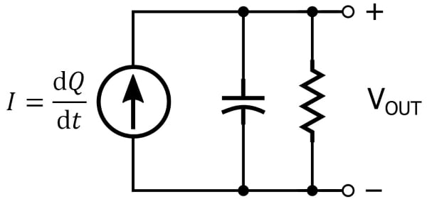
I recently wrote an article that presents an equivalent circuit for piezoelectric transducers. It consists of a current source and a parallel capacitor, and a parallel resistor can be included to account for the fact that charge generated by the piezoelectric material will diminish over time.
The Amplification Question
The charge produced by a piezoelectric material in response to mechanical stress is quite small. Typical values for the piezoelectric coefficient are in the tens or hundreds of picocoulombs per newton. One newton is a significant amount of force, whereas 100 picocoulombs is a miniscule amount of charge. Clearly, then, we will need an amplifier that can convert the sensor’s charge into a usable signal.
Another issue is the mathematical relationship between the output voltage of the amplifier and the physical change in force, pressure, or acceleration. The force applied to the piezoelectric material is proportional to charge, not current. If we convert the sensor’s current into a voltage, the resulting signal is proportional to the rate at which the applied force changes, rather than to the applied force itself.
If you’ve read the preceding article, you know that the equivalent circuit for a piezoelectric sensor has an output voltage that is proportional to applied force. Why, then, can’t we simply use a voltage amplifier? Well, it is possible to use a voltage amplifier, but in many cases it’s not the preferred solution. The problem is cable capacitance.
Dealing with Interconnect Capacitance
The expression for VOUT given in the previous article was the following:
$$V_{OUT} = \frac{1}{C}\int \frac{\text{d}Q}{\text{d}t}\ \text{d}t=\frac{Q}{C}$$
We presented this formula in the context of the equivalent circuit that consists of a current source and the parallel capacitance created by the electrodes. "C" in the equation refers to this capacitance, which is associated with the physical structure of the piezoelectric device and as far as I know does not, under typical operating conditions, exhibit problematic variations.
However, any other source of capacitance that is in parallel with the sensor will contribute to the “C” term in the expression above; that is to say, additional parallel capacitance associated with the cable that connects the piezoelectric device to the amplifier will change the relationship between applied force and VOUT. The capacitance of the sensor is not large (I’ve seen numbers in the hundreds of picofarads and in the low nanofarad range); thus, small changes in cable capacitance—such as those caused by replacing or even rearranging the cable—can have a significant effect on the system. The bottom line is that voltage-mode amplification should be considered only when the sensor is close to the amplifier circuit. Also, the amplifier’s input capacitance affects the charge-to-voltage relationship in the same way as the cable capacitance, so different amplifiers (even if they have the same gain) can produce different output signals.
So far this sounds like a troublesome design task, but actually there’s a simple circuit that does just what we need. It’s called a charge amplifier.
Charge Amplifiers for Piezoelectric Sensors
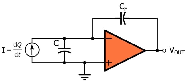
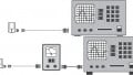
A charge amplifier is an integrator with very high input impedance. The integration functionality converts charge into voltage, and the high input impedance ensures that the small amount of charge generated by the piezoelectric transducer is not lost through leakage.
Charge to Voltage
The charge amplifier shown above reminds me of a transimpedance amplifier but with a capacitor instead of a resistor in the feedback path, and I think that this observation is helpful when you’re first pondering the functionality.
A transimpedance amplifier accepts an input current and multiplies it by the resistance in the feedback path, which not only increases the amplitude but also converts the current into a voltage. The charge amplifier does something similar, but the use of capacitance instead of resistance in the feedback path creates an output that is proportional not to the instantaneous current but rather to the accumulation of current over time. In other words, the output tells us something about the integral (with respect to time) of current rather than the magnitude of the current at a given moment.
In an application such as a photodiode amplifier, where the sensor’s output signal is a current that is proportional to light intensity, we have no need for information regarding the integral of the signal. However, with a piezoelectric sensor, the quantity being measured is proportional to charge, and the input signal is a current equal to the derivative of charge, and thus the integral of the input signal gives us the information we need, namely, charge.
This is the expression for the output voltage of the charge amplifier:
$$V_{OUT}=\frac{1}{C_F}\int -I\ \text{d}t=-\frac{Q}{C_F}$$
Note the following:
- The input current is multiplied not by CF but by 1/CF. This contrasts with the gain of a transimpedance amplifier, which is equal to the feedback resistance RF (not 1/RF).
- The gain depends only on the feedback capacitance; it is not affected by the cable capacitance or the internal capacitance of the sensor.
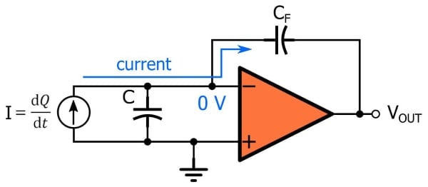
- If the sensor’s current is flowing toward the op-amp’s inverting input terminal, the charge amplifier produces a negative voltage. We can see why this is the case if we recall that an insignificant amount of current flows into the op-amp and that the inverting terminal is at virtual ground: the only path for the sensor’s current is around the op-amp and through the feedback path, and for current to flow from the inverting terminal (which is at 0 V) toward the output terminal, the output voltage must be negative.
- The presence of virtual ground at the inverting terminal also explains why the circuit is not affected by cable capacitance or sensor capacitance. Both of these capacitances are in parallel with the current source, which means that they have ground on one side and virtual ground on the other side. Thus, no current flows through them and they don’t influence the operation of the circuit.
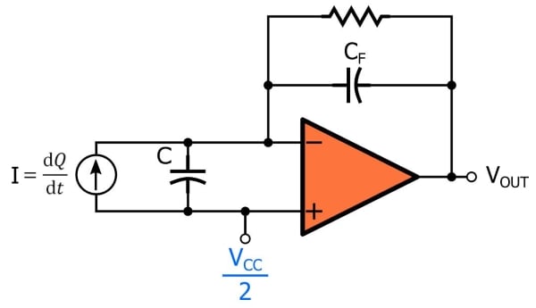
A Realistic Charge Amplifier
The idealized circuit shown above is not a practical implementation because the op-amp’s input bias current will charge up the capacitor and cause the amplifier to saturate. We can remedy this situation by adding a resistor (which provides a discharge path) in parallel with the capacitor. Also, you can adapt the circuit to a single-supply environment by connecting the noninverting terminal to a reference voltage such as VCC/2.
Conclusion
I hope that you now understand how charge amplifiers work and why they are beneficial in systems that use piezoelectric sensors. If you have experience in this field and want to share some tips or experiences, feel free to leave a message in the comments section below.


Insulation resistance on the input side is important because leakage reduces sensitivity. Noise pickup is also a possible problem. We used charge amps in a shock wave sensor that was a 1cm diameter of PVDF. It seems that metalized polarized PVDF is a challenge to produce with uniform properties during large production runs. We required uniformity withing 1% on sensitivity and tempco. The supplier could not do better than +/- 50%. Oh Well.