 Facebook
 Google
 GitHub
 Linkedin
Bridge Amplifiers for Single-Supply Applications
This article describes the bridge-amplifier configuration and explains why it’s especially handy when you don’t have a negative voltage supply.
This article describes the bridge-amplifier configuration and explains why it’s especially handy when you don’t have a negative voltage supply.
Supporting Information
Why Single Supply?
There are a few different terms used to refer to a system in which the designer has access to positive and negative voltage rails: bipolar, symmetrical, dual-supply, split-supply. Whatever you want to call them, I like them; analog circuits are more straightforward and (in my opinion) more mathematically coherent when a signal can actually go below ground.
However, the inescapable fact is that the dual-supply system is usually a persona non grata in the world of modern electronics. The reason for this is simple enough: generating a negative voltage supply requires additional circuitry, which means more design time, higher cost, and a larger PCB; thus, if system requirements can somehow be met without recourse to a negative supply rail, all the better. The alternative to additional circuitry is a second battery; besides being applicable only to battery-powered equipment, this approach still introduces cost and bulkiness that could be eliminated by means of clever single-supply circuit design. The trend favoring single-supply systems is aptly demonstrated by the fact that Texas Instruments has a 46-page publication (PDF) dedicated exclusively to single-supply op-amp circuits.
Note: There is no law stating that a dual-supply system must have positive and negative supply voltages that are equal in magnitude (i.e., symmetrical). However, symmetrical supplies are the norm with amplifier circuits, and a discussion of dual-supply or split-supply systems may include the assumption that the supply voltages are symmetrical.
The Bridge Amplifier
One thing that can be difficult in a single-supply environment is generating high-power AC output signals. Let’s take a look at a circuit that can help with this task:

As you can see, the input signal is fed to two op-amp circuits, one noninverting, the other inverting; the resistors are chosen so that both amplifiers have the same gain magnitude. The load is connected between the outputs of the two amplifiers; note that the load is “floating,” i.e., it has no direct connection to the ground node. As you have probably figured out by now, the bridge amplifier results in a factor-of-two increase in the voltage across the load:
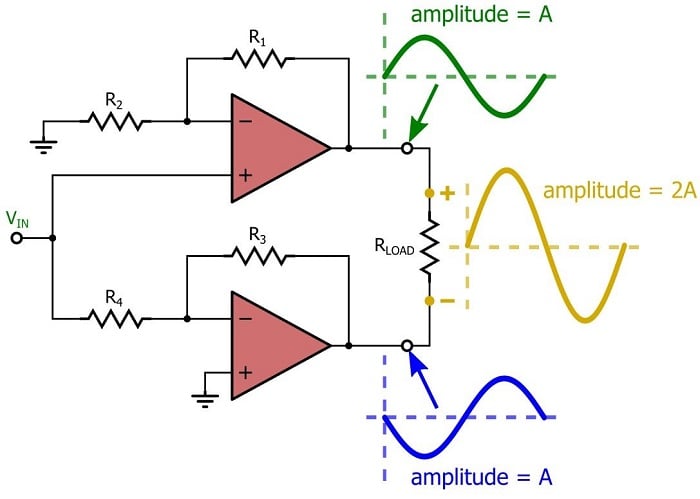
The standard bridge amplifier shown here is not a single-supply circuit. Both op-amps have an input terminal that is referenced to ground; thus, a ground-referenced sinusoidal input signal would require both op-amps to generate negative output voltages, and this of course, is quite impossible when the op-amp’s negative-supply pin is connected to ground.
The Single-Supply Version
The following circuit adapts the bridge configuration to a single-supply environment:

The essential characteristic of a single-supply op-amp circuit is the bias voltage that creates a mid-supply reference (just as ground potential serves as a mid-supply reference in dual-supply systems). The bias voltage doesn’t have to be at mid-supply, but this is the usual choice when dealing with sinusoidal signals because a mid-supply bias ensures that the output signal has equal ability to swing “positive” and “negative” (“positive” meaning above the bias voltage and “negative” meaning below the bias voltage).
There are various ways to bias a single-supply op-amp circuit. The most straightforward approach, in my opinion, is the one shown in the above diagram—you configure the circuit as an inverting amplifier and apply VBIAS to the positive input terminal. This is why the single-supply bridge amplifier uses two inverting amps, whereas the standard bridge amplifier uses a noninverting amplifier and an inverting amplifier.
Biasing a noninverting amp is awkward—whether you apply the bias to the positive or negative input terminal, the relationship between the bias voltage and the output voltage is more complex compared to that of the inverting configuration. Also, if you use a resistive divider to generate the bias voltage, the resistors in a noninverting amp interact with the resistors in the divider and thereby make your life even more complicated than it already is. The inverting configuration allows you to connect the bias voltage directly to the very-high-impedance op-amp input terminal, and thus you can use a resistive divider without fear of consternation:

Finally, you probably noticed that the input to one of the op-amps is taken not from the input signal itself but rather from the output of the other op-amp. The whole point of the bridge amplifier is to generate both an inverted and a noninverted output signal, and thus the cascaded-amplifier arrangement is a simple solution to the problem of having two inverting amplifiers.
More Voltage → More Power
There are two prominent benefits associated with the bridge amplifier. The first one we’ll discuss is the following: a bridge amplifier allows you to deliver significantly more power to a load. How much more? Well, we know that instantaneous AC power can be expressed as follows:
\[P_{LOAD}=\left(\frac{V_{PEAK}}{\sqrt{2}}\right)^{2}\times\frac{1}{R}\]
Thus, power is proportional to the square of the peak voltage. The bridge configuration doubles the voltage across the load; therefore, it offers a factor-of-four increase in power delivered to the load. Maybe you’re wondering, though—why can’t we just use a single op-amp and then increase the gain to get more voltage? Why bother with the bridge configuration? These are good questions, and the response is as follows: the bridge amplifier quadruples the maximum PLOAD that you can achieve for a given supply voltage. In other words, the bridge amplifier is particularly useful when you are trying to get as much power as possible from your supply rail.
In this age of low-voltage systems, you may find that the supply voltage is the limiting factor in how much power you can send to the load. Let’s assume that the load resistance is fixed, so you can’t increase power by reducing RLOAD, and let’s also assume that you have plenty of current available from your power supply. In this case, your 3.3 V supply is holding you back—you could easily deliver more power if only you had a little more supply voltage. Well, this is where the bridge amplifier comes in: same voltage rail, four times as much power.
No Coupling Cap Needed
My favorite thing about the bridge amplifier is that it allows you to eliminate the DC offset without eliminating the DC offset . . . or something like that. Let’s say you have a speaker that you need to drive from your single-supply circuit. All the audio signals have a DC offset that keeps the negative portions of the sinusoid above ground. But the signal we send to the speaker should be pure AC; a DC offset in an audio signal reduces dynamic range and contributes to distortion. This is often accomplished with a DC-blocking (aka AC-coupling) capacitor, but there are drawbacks to this approach: First, the capacitor may need to be quite large—easily hundreds of microfarads—to avoid attenuation of low-frequency signal components. Second, you have to worry about transient effects associated with charging or discharging the DC-blocking cap, such as the “click-and-pop” artifacts that afflict audio playback.
Fortunately, no blocking cap is needed when you have a bridge amplifier. The complementary nature of the inverted and noninverted waveforms is such that the DC offset of one signal can cancel out the DC offset of the other:

Conclusion
We looked at the standard bridge amplifier as well as a single-supply-compatible variant, and we discussed two major advantages offered by the bridge configuration. As one of my professors once said in reference to some mathematical concept that I can’t quite remember, fold this up and keep it in your hip pocket; a bridge amplifier may prove quite useful when you need to deliver significant amounts of AC power from a low-voltage or single-supply system.


In the image above the conclusion, aren’t the negative and positive voltages totally cancelling each other, producing a flat output? Or are they phase shifted?