Facebook
 Google
 GitHub
 Linkedin
Understanding Piezoelectric Accelerometer Basics
Learn about piezoelectric accelerometers, namely the piezoelectric effect, how piezoelectric materials generate electricity, the different accelerometer design modes, and their upper and lower frequency limits.
Piezoelectric accelerometers are typically used in vibration and shock testing. These devices can be well suited for measuring high-frequency acceleration signals found in hydraulic and pneumatic perturbations, impulse (impact) forces, machinery and equipment vibrations, pyrotechnic shocks, etc.
In this article, we’ll get familiar with the basic concepts of these sensors.
Understanding Piezoelectric Sensors: The Piezoelectric Effect
The first key aspect of piezoelectric accelerometers is the piezoelectric effect. In general, a piezoelectric material can produce electricity when subjected to mechanical stress.
Conversely, applying an electric field to a piezoelectric material can make it deform and generate a small mechanical force. Although most EEs are familiar with the piezoelectric effect, the details of this interesting phenomenon sometimes aren’t fully understood.
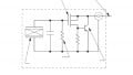
A deeper insight into this effect can help us better understand the working of piezoelectric sensors. Figure 1 shows the effect of an external mechanical force on a piezoelectric material.
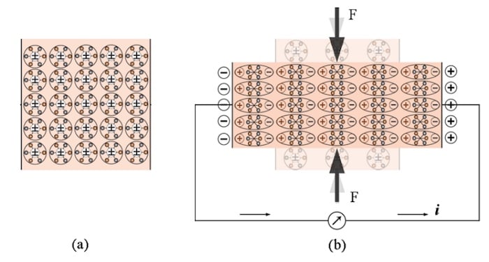
Figure 1. Piezoelectric materials without mechanical stress (a) and with stress (b). Image (adapted) used courtesy of Felix Levinzon
As shown in Figure 1(a), with no mechanical stress, the center of the negative and positive charges of the molecules coincide, which means that the molecules are electrically neutral.
Applying a mechanical force, as depicted in Figure 1(b), deforms the structure and separates the center of the positive and negative charges of the molecules creating many small dipoles in the material.
As you can see, some fixed charges appear on the surface of the piezoelectric material. The amount of the produced electric charge is proportional to the applied force.
How Piezoelectric Materials Generate Electric Current
Piezoelectrics are a class of dielectric materials. They are insulating or very poor conductors of electric current. However, with two metal electrodes deposited on the opposite surfaces of the piezoelectric material, we can use the electric field generated by the piezoelectric effect to produce electricity.
If we connect the two electrodes together through a wire as depicted in Figure 1(b), the free electrons in the conductor flow toward the positively charged electrode and an electric current are created. This current flow accumulates the free electrons on the positive electrode and creates an electric field in the opposite direction of the original field produced by the piezoelectric effect.
This effect explains why the electric current produced by a static force can last only for a short period of time. The current continues until the electric field from the accumulation of the free electrons cancels the field from the piezoelectric effect.
Now, if we remove the external force, the material returns to its original shape, the electric field from the piezoelectric effect disappears, which means a current in the opposite direction flows through the wire.
Structure of Piezoelectric Accelerometers
In a piezoelectric accelerometer, a piezoelectric element is used to connect a known quantity of mass, commonly referred to as the proof mass, to the accelerometer body.
When the sensor frame accelerates because of an external force, the proof mass tends to “stay back” due to its inertia and deforms the piezoelectric element slightly. This makes the piezoelectric element produce a charge output that can be measured to determine the input acceleration.
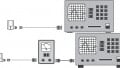
Figure 2 depicts some common mechanical designs of piezoelectric accelerometers. The three fundamental designs are the compression mode, the shear mode, and the flexural.
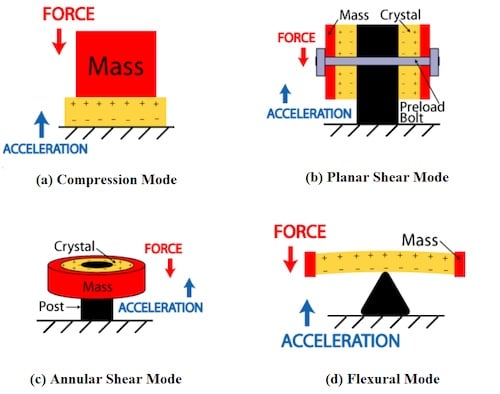
Figure 2. Some mechanical designs of piezoelectric accelerometers. Image (adapted) used courtesy of PCB Piezotronics
The figure also illustrates the force exerted by the proof mass on the piezoelectric element as well as the acceleration applied to the sensor body.
Accelerometer Mechanical Design Modes Pros and Cons
The mechanical configuration can affect the sensor performance in several different ways. It can have an impact on the sensor sensitivity, bandwidth, temperature susceptibility, as well as susceptibility to the sensor base strain.
For example, with a compression mode sensor, we have a stiff structure that can offer a relatively higher frequency range. However, in a compression mode sensor, the piezoelectric material is in intimate contact with the base of the housing and the sensor is sensitive to base bending and thermal expansion.
That’s why this type might not be suited for use in a thermally unstable environment or on a metal structure that might bend.
In a shear mode sensor, the piezoelectric element experiences shear deformation when subjected to acceleration. This type also has a high-frequency range while being less susceptible to base bending and temperature variations. Shear mode accelerometers are the most popular configuration.
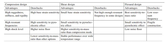
The flexural type has a less stiff structure and thus, offers a lower frequency range. With this type, the piezoelectric element experiences a relatively larger strain for a given value of acceleration. As a result, this structure offers a higher sensitivity; however, it is relatively fragile. The table below provides a comparison of these three types.
Table 1. Comparison of three piezo accelerometer modes. Image used courtesy of Felix Levinzon
Piezoelectric Accelerometer Range: The Upper-frequency Limit
Just like a MEMS accelerometer, the operation of a piezoelectric accelerometer is based on Newton’s second law of motion. The proof mass and the piezoelectric element can be modeled by a mass-damper-spring structure.
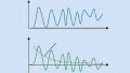
The mass displacement can be described by the classical second-order differential equation of motion. The resonance behavior of this mechanical system defines the upper-frequency limit of the piezoelectric accelerometer, which can be seen in Figure 3.
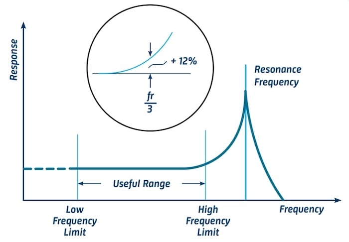
Figure 3. The resonance frequency of a MEMS accelerometer. Image used courtesy of BKSV
As a rule of thumb, if we limit the frequency of the input acceleration to below one-third of the accelerometer's resonant frequency, the response error should be less than about 12%.
To learn more about the frequency response of a mass-damper-spring system, please see this article.
Piezoelectric Accelerometer Range: The Lower Frequency Limit
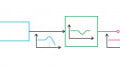
As shown in Figure 4, piezoelectric accelerometers are not capable of a true DC response and cannot perform true static measurements.
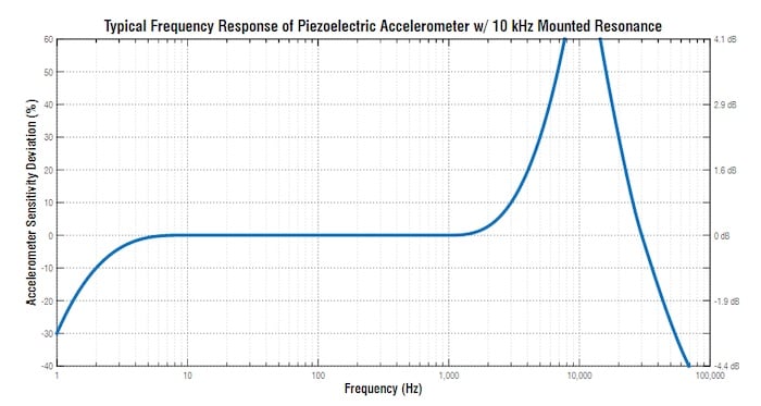
Figure 4. Graph showing the frequency response for piezoelectric accelerometers with 10 kHz mounted resonance. Image used courtesy of Endaq
The lower frequency limit of a piezoelectric accelerometer is determined by the lower cut-off frequency of the amplifier that follows the sensor.
With voltage mode amplifiers, the lower frequency limit is also affected by the parameters of the piezoelectric element and the capacitance of the cable placed between the accelerometer and amplifier.
The lower cut-off frequency of a properly designed piezoelectric accelerometer can be below 1 Hz. However, it should be noted that these sensors are not capable of a true DC response.
For example, they cannot measure the force exerted by gravity. Although this might seem like a big issue at first, it should be noted that many applications do not require measuring acceleration signals in the range of fractions of a hertz. Consequently, in many applications, the lack of a true DC response is not really a drawback.
It’s also interesting to note that, apart from the lower cut-off frequency limitations of the amplifier, piezoelectric-based sensing is not inherently suitable for true DC measurements. This is due to the fact that the internal resistance of the sensor (as well as the input resistance of the signal conditioning circuitry) can create resistance in parallel with the sensor.
This parasitic resistance can create an undesired leakage path for the output current of the sensor and set a lower limit for the usable frequency range of the system.
In the next article, we’ll look at the charge amplifiers that are commonly used to convert the charge output of a piezoelectric accelerometer to a usable voltage signal.
To see a complete list of my articles, please visit this page.
Related Content