 Facebook
 Google
 GitHub
 Linkedin
Filtering Accelerometer Output for Noise Suppression and Bandwidth Improvement
Learn how a low-pass filter can improve the noise performance of the accelerometers as well as how to extend the bandwidth of a MEMS accelerometer using a custom notch filter.
In a previous article, we looked at the frequency response of the mass-damper-spring system used in a typical MEMS accelerometer. The signal produced by the mechanical part of the accelerometer is typically processed by an internal amplifier, synchronous demodulator, and finally a low-pass filter.
In this article, we’ll see that the low-pass filter can improve the noise performance of the accelerometer. We’ll also discuss how a custom notch filter can extend the bandwidth of a MEMS accelerometer.
Frequency and Bandwidth of MEMS Capacitive Accelerometers
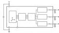
Figure 1 shows the simplified block diagram of a MEMS capacitive accelerometer.
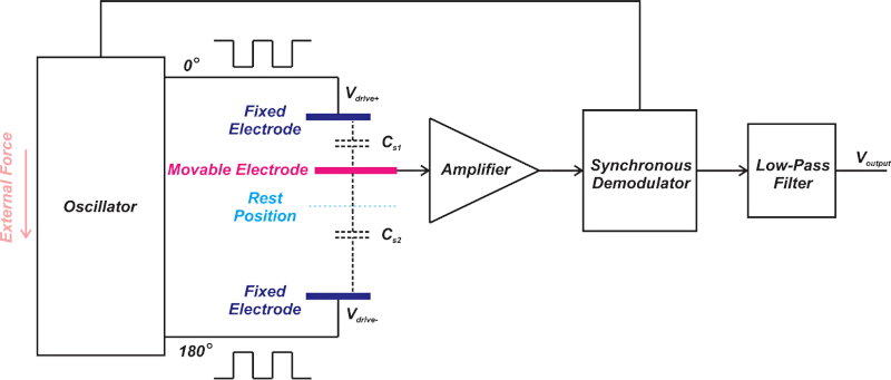
Figure 1. A block diagram for a MEMS capacitive accelerometer.
As you can see, a MEMS accelerometer consists of several different mechanical and electrical components.
Each component contributes to the overall transfer function and can limit the overall system bandwidth.
Part of the system transfer function is related to the mass-damper-spring system that controls the position of the movable electrode. The electrical signal produced by the capacitive sensing structure is further processed by the internal amplifier, synchronous demodulator, and finally the low-pass filter.
The magnitude response of a mass-damper-spring system with ωn = 2π x 500 Hz and Q = 5 is shown in Figure 2.
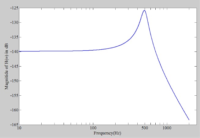
Figure 2. The magnitude response of a mass-damper-spring system.
The response magnitude changes with frequency.
To keep the response error below a specified maximum error, we should use the accelerometer at frequencies much lower than the sensor resonant frequency.
For example, with the response depicted above, we need to use the accelerometer at frequencies below 100 Hz to keep the response error below about 5%. The usable frequency range is much lower than the resonant frequency of the system which is 500 Hz.
Limiting Bandwidth to the Maximum Frequency Using a Low-pass Filter
While we use an accelerometer at frequencies much lower than the system resonant frequency, the response magnitude of a mass-damper-spring system doesn’t start to roll off up to about the resonant frequency.
For example, in Figure 2, the response magnitude is equal to or greater than the response magnitude at DC (or low-frequency) accelerations up to about 700 Hz. This is why any unwanted acceleration signals (such as mechanical noise components) in the range of 100 Hz up to about 700 Hz will be sensed by this mass-damper-spring system.
The total noise power at the output of a system directly depends on the system bandwidth. That’s why we need a low-pass filter to limit the bandwidth to the maximum frequency needed by the application. This maximizes the resolution and dynamic range of the accelerometer.
Figure 3 shows how the bandwidth of the ADXL335 is set by placing capacitors at the accelerometer outputs.
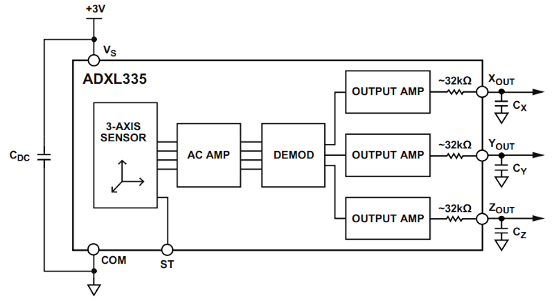
Figure 3. A block diagram of ADXL335. Image used courtesy of Analog Devices.
The 32 kΩ internal resistors along with the external capacitors lead to a single-pole, roll-off characteristic with the RMS noise given by:
$$RMS\,Noise = Noise\,Density\times\sqrt{BW\times1.6}$$
where BW is the bandwidth of the system that is set by the RC filter and is given by:
$$BW = \frac{1}{2\pi\times 32 k\Omega\times C_{external}}$$
In this equation, Cexternal denotes the external filter capacitors (CX, CY, CZ) at the XOUT, YOUT, and ZOUT pins. In addition to improving the noise performance, a low-pass filter also acts as an anti-aliasing filter for a subsequent A/D converter.
While placing a low-pass filter after the accelerometer is common, we might need a notch filter in certain high-frequency applications to extend the accelerometer bandwidth. We’ll look at this in the rest of the article.
The Need for a Wide Bandwidth Accelerometer
In certain applications, such as the vibration analysis of a mechanical system, we might need to measure acceleration signals with frequencies as high as the resonant frequency of a MEMS accelerometer.
Vibration analysis is a fundamental step for reliability evaluation, machine fault diagnosis, and prognosis. Vibrations of a machine can cover a wide spectrum including the range of about 10 Hz to 10 kHz. Different frequency components in this range might be related to different types of machine faults for a given application.
Now, how can we measure a frequency range comparable with the accelerometer resonant frequency while we know that the mass-damper-spring system cannot provide a constant magnitude response over such a large frequency range?
Extending the Bandwidth of an Accelerometer Using a Notch Filter
To extend the system bandwidth to the resonant frequency of the sensor, the reference design “MEMS-Based Vibration Analyzer with Frequency Response Compensation” from Analog Devices suggests placing a custom notch filter after the accelerometer.
The basic idea is illustrated below in Figure 4.
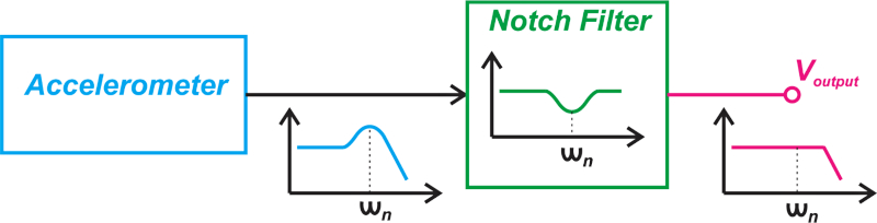
Figure 4. Block diagram showing the use of a notch filter with the accelerometer.
This solution is based on the assumption that the accelerometer frequency response exhibits peaking around the resonant frequency (quality factor > 0.5), which is the case with many commercial MEMS accelerometers.
The notch filter attenuates the frequency range where there is an increase in the accelerometer gain. Ideally, the notch filter should be able to flatten the frequency response of the accelerometer and allow us to more easily measure high-frequency vibrations.
Note that the notch frequency, i.e., the frequency at which the filter exhibits its maximum attenuation, should be tuned to the resonant frequency of the accelerometer. And, the filter attenuation at the notch frequency should be equal to the gain peaking of the accelerometer.
Figure 5, below (from the Analog Devices reference design mentioned above), shows how effective this method can be in practice.
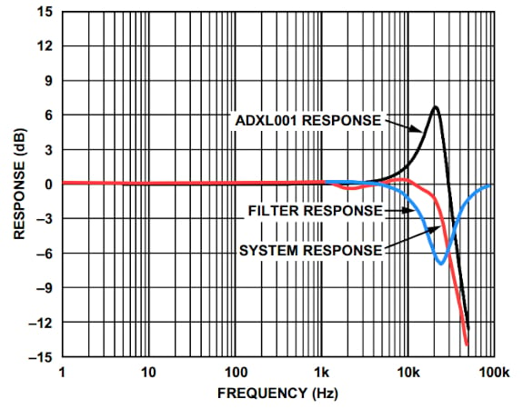
Figure 5. Response vs. frequency using a notch filter with the accelerometer. Image used courtesy of Analog Devices
The black curve shows the frequency response of the ADXL001 that exhibits 7 dB of peaking at 22 kHz.
Using a notch filter with a notch depth of 7 dB at 22 kHz (shown as the blue curve), we observe that the overall system exhibits a 3 dB bandwidth of about 22 kHz.
This technique is suitable for bearing analysis, engine monitoring, and shock detection applications.
The Wide Bandwidth Doesn’t Come Without a Price!
First, it should be noted that the extended bandwidth is achieved at the cost of adding an additional custom filter to the signal chain. Besides, with the above technique, we’ll lose some of the rated acceleration range of the sensor.
For example, assume that the measurement range of the accelerometer is ±70 g; thus, a DC (or low-frequency) acceleration of +70 g makes the sensor output swing all the way to the positive rail.
Since the accelerometer gain increases as we get closer to the resonant frequency, a relatively smaller acceleration can hit the positive swing limitation at the resonant frequency.
In the case of the example depicted in Figure 5, the sensor frequency response peaks by 7 dB at the resonant frequency which corresponds to an increase by a factor of 2.24 compared to the low-frequency gain of the sensor.
Therefore, using the sensor over the frequency range from DC to the resonant frequency, the maximum acceleration that can be measured without the sensor output being saturated is +70 g divided by 2.24 which is about +31 g.
Note that, to apply the above technique, the internal signal conditioning of the accelerometer should support a bandwidth beyond the resonant frequency of the sensor.
To see a complete list of my articles, please visit this page.
Related Content


Clear and very helpful, many thanks. I will definitely bookmark your list of other articles.
Yes, very clear and helpful. Nice article.