Facebook
 Google
 GitHub
 Linkedin
Understanding Radiated Electromagnetic Compatibility Tests
This article is the second in a two-part series that reviews the basics of electromagnetic compatibility tests. We'll now turn our attention to radiated EMC tests.
In the first article of this two-part series, we introduced the need for electromagnetic compatibility (EMC) tests and standards. Since it is impossible to test all the equipment in the world at the same time, standardized ways of testing all the systems going to the market are defined.
The first article talked about tests for conducted EMC, which have two goals: first, verify that the power emitted through the wiring harness lines is below the limits, and second, verify that equipment can support some amount of injected current without being disturbed.
Part Two of this series introduces tests for radiated EMC, which have the same goals as conducted EMC tests. But instead of testing the wired medium, tests for radiated EMC deal with the electromagnetic spectrum.
The Goals of Radiated EMC Tests
Radiated EMC tests have two goals. One is to measure the radiated energy coming out of a device and the wiring harness connected to it. The other goal is to check that the device under test (DUT) can keep working in a normal operation mode, even when an electromagnetic field is applied directly to it.
Energy can be transmitted in the form of electromagnetic waves. According to Maxwell’s equations, any current circulating through a conductor generates a magnetic field. During radiated emissions tests, this generated field amplitude has to be below a specified limit.
Conversely, any radiated field falling upon a conductor will provoke a circulating current. When performing radiated susceptibility tests, the DUT is monitored at all times, allowing engineers to analyze the moment at which a failure occurs. As in conducted tests, radiated tests use a ground plane to give a return path to common mode currents.
Antennas for Radiated Tests
For both emission and susceptibility tests, different types of antennas are used. The selected model will depend on the frequency range and the desired radiation pattern.

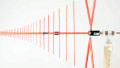
Biconical antenna for 20 MHz to 330 MHz. Image used courtesy of A.H. Systems, inc
The antenna resonant frequency (the frequency at which the antenna will radiate the maximum energy), is related to the antenna length. Hence, to cover all the frequencies of EMC tests, antennas are changed when shifting from one frequency range to another.

Horn antenna for 1 GHz to 18 GHz. Image used courtesy of ATEC
What are Radiated Emissions Tests?
In radiated emissions tests, the electromagnetic waves coming out from the DUT are measured. Emissions can be produced intentionally—for example, in a device using Wi-Fi—but most of them are unintentionally caused by currents circulating through the internal components and the wiring harnesses.
The methods reviewed here are based on CISPR 25 and the ISO 11452-2, which define the limits and procedures for the measurement of radio disturbances starting from 150 kHz.
All the equipment must be placed inside an anechoic chamber, which attenuates all the emissions in all the desired bandwidth. Absorber materials are added to the walls for the removal of reflected energy.

Car being tested in an anechoic chamber. Image used courtesy of thisisengineering
A list of antennas used in EMC tests is shown in the table below. When possible, tests are performed with both vertical and horizontal polarizations.
| Frequency Band | Antenna Type |
|---|---|
| 150 kHz–30 MHz | 1 m vertical monopole |
| 30 MHz–200 MHz | Biconical |
| 200 MHz–1000 MHz | Log-periodic |
| 1000 MHz–1500 MHz | Horn or log-periodic |
Depending upon the band frequency, antennas are aligned with the DUT or at the midpoint of the wiring harness.
When designing a new product, designing the wiring harness and the signal distribution properly is as important as the product design itself. Since wires carry current and can be electrically long, they can function as undesired antennas that can provoke unwanted emissions and make tests fail.

Radiated emissions test set-up. Image used courtesy of Texas Instruments
Once all the equipment is placed inside the anechoic chamber and the DUT is configured to run in its regular functioning mode, emissions are measured using an EMI receiver or a spectrum analyzer.
After scanning all the frequency ranges, engineers must compare measured levels with those required by the CISPR 25 standard. If measured emissions are above the limits, the test rules the DUT a failure, even if it was only tested at one frequency. These limits can be as low as 12 dBµV/m and as high as 61 dBµV/m.
Radiated Susceptibility Test
Any equipment installed close to other equipment is susceptible to the radiation generated by surrounding equipment as well as any power or communication lines. This radiation can cause malfunctioning or even destroy an electronic device if it is not properly protected.
Depending on the device, short-term malfunctioning may be permissible (for instance, in a display) or completely unacceptable (for instance, in a pacemaker). To prevent these errors, electromagnetic radiation is generated at many different frequencies toward the DUT, which is configured to work as it will in a regular situation.
The test setup for radiated susceptibility tests, also known as radiated immunity tests, is quite similar to the one used for radiated emissions tests. The main difference is that power is injected through an antenna and then electromagnetic fields are directed at a DUT and its wiring harness.
The DUT is configured to work in all its functioning modes—e.g., normal, low-power, active communication—and then electromagnetic fields are applied to it. If at some frequency, the DUT being tested experiences any malfunctioning, relevant details related to the malfunction will be recorded.
Conclusion
In this series, we have reviewed the two main types of EMC tests: conducted and radiated tests. EMC tests are compulsory for every product to be sold in any part of the globe.
Depending on the country, sector, and type of product, different test setups and procedures are used. To prepare for new product development and to pass EMC tests, it's important to have a solid understanding of these applied standards.