 Facebook
 Google
 GitHub
 Linkedin
Understanding Total Harmonic Distortion (THD) in Power Systems
This article describes the cause and effect of total harmonic distortion (THD) in power systems. Some means of improving THD are also discussed.
Total harmonic distortion (THD) is an important aspect in power systems and it should be kept as low as possible. Lower THD in power systems means higher power factor, lower peak currents, and higher efficiency. Low THD is such an important feature in power systems that international standards such as IEC 61000-3-2 set limits on the harmonic currents of various classes of power equipment.
Introductions to AC circuit analysis typically focus on power factor as being determined by the phase relationship between the voltage and current in a circuit while generally ignoring the effect of THD on power factor. Specifically:
$$PowerFactor = cos(\theta_v - \theta_i)$$ eqn. 1
Where $$\theta_v$$ is the phase of the voltage and $$\theta_i$$ is the phase of the current.
This is not the full definition of power factor and this equation, which is called the displacement factor, is only true if both the voltage and the current are completely sinusoidal. The displacement factor aspect of power factor is well covered here and here.
To be fair, most people new to AC circuits are introduced to the proper definition of power factor, but after this introduction they typically focus only on the displacement factor and not the effect of THD. The full definition of power factor is:
$$PowerFactor = \frac{ P_{avg}}{(V_{rms})(I_{rms})}$$ eqn. 2
Power factor is applicable to circuits with the general form of Figure 1 where there is an AC voltage source that provides an AC current for some kind of load. It is the nature of the load that determines the nature of the current and therefore the power factor.
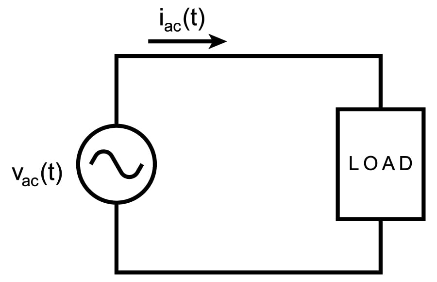
Figure 1. AC voltage source with load
Power Factor without THD
If the voltage and current are purely sinusoidal, then the RMS voltage and current can be determined directly from the peak voltage and current:
$$V_{rms} = \frac{V_{pk}}{ \sqrt{2}}$$ and $$I_{rms} = \frac{I_{pk}}{ \sqrt{2}}$$
If the load is purely resistive, then the average power and apparent power would be equal and the power factor would be 1. If the load also has capacitive and/or inductive elements then the phase difference between the voltage and current could be measured to determine power factor from the equation 1. Figures 2 to 4 show three types of loads along with the relationship between the phases of the voltage and current as well as the relative power factors. Remember, these power factors can be calculated directly from equation 1 because the voltage and current are purely sinusoidal.
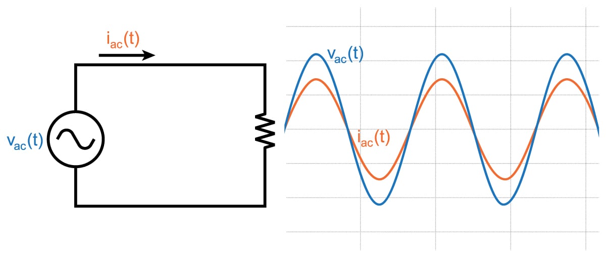
Figure 2. Resistive load with waveforms (Power Factor = 1. Voltage and current are in phase)
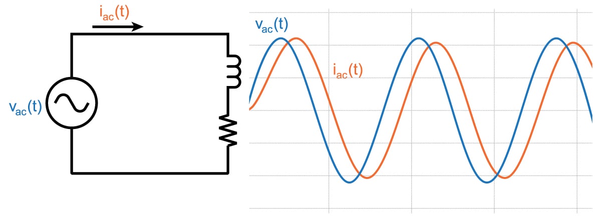
Figure 3. Resistive and inductive load with waveforms (Power Factor < 1 and voltage leads current)
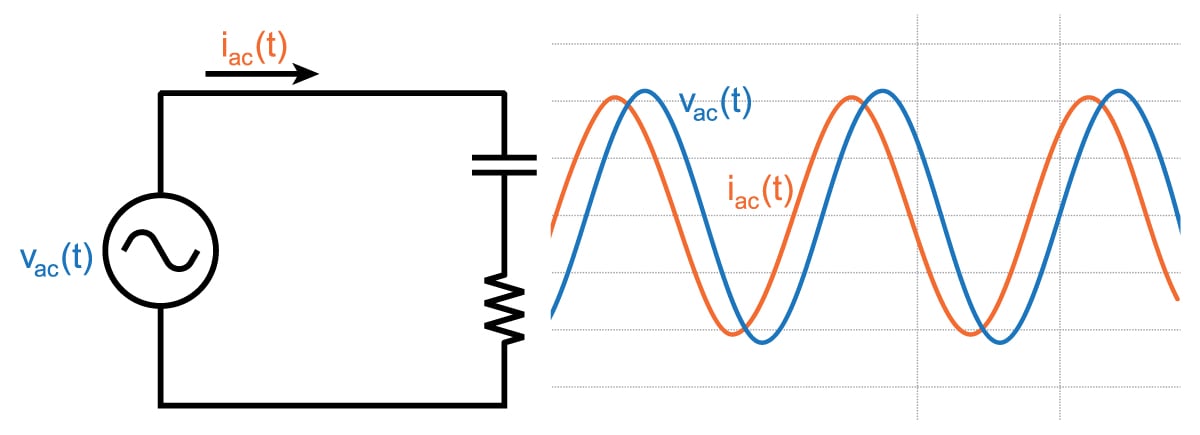
Figure 4. Resistive and capacitive load with waveforms (Power Factor < 1 and current leads voltage)
Improving the power factor in systems like those in Figures 3 and 4 requires placing a component with the opposite amount of reactance into the system to counteract the reactance already in the system. This type of compensation is explained here.
THD in Power Factor
Most electrical systems do not have loads with only resistors, inductors and capacitors. Most loads also include power conversion of some kind (such as AC/DC, DC/AC, or DC/DC converters) or some other kind of non-linear load (e.g. fluorescent lighting). These power converters and other non-linear loads change the nature of the current so that it is no longer sinusoidal. Switching power supplies, in which the power element rapidly transitions between a fully-on and a fully-off state, can be especially non-linear. Tricks such as filtering or adding control systems to force current flow to follow a reference signal are often used to reduce the effect of the switching. Even "linear" AC/DC converters significantly change the nature of the current so that it is no longer sinusoidal. Current in these types of converters is "bursty", and this article describes exactly why that is the case.
Since the current in these non-linear systems is still periodic (just not sinusoidal), this change in the nature of the current can be described in terms of the harmonic distortion of the current. Each one of the harmonics in the current has an RMS value, so calculation of the RMS current of the whole signal (as you would need to do when calculating power factor) involves summing the RMS value of each harmonic.
$$ I_{rms} = \sqrt{I_{dc}^{2} + \sum_{k=1}^{\infty}I_{k\_rms}^{2}} $$ eqn. 3
If you assume that you have a good voltage source that provides a sinusoidal voltage, then there is no voltage at frequencies other than the fundamental so real power will only be provided at the fundamental frequency:
$$P_{avg} = V_{1\_rms} \times I_{1\_rms} \times (DisplacementFactor)$$ eqn. 4
On the other hand, apparent power which is equal to $$V_{rms}I_{rms}$$ will include all of the current harmonics, so the term in the denominator of Equation 2 will be higher than what you would expect if you are only using the current at the fundamental frequency. Taking eqn. 3 and 4 and plugging them into eqn. 2 gives:
$$PowerFactor = \frac{ V_{1\_rms} \times I_{1\_rms} \times (DisplacementFactor)}{V_{1\_rms}\times\sqrt{I_{dc}^{2} + \sum_{k=1}^{\infty}I_{k\_rms}^{2}}}$$
$$= \frac{I_{1\_rms}}{\sqrt{I_{dc}^{2} + \sum_{k=1}^{\infty}I_{k\_rms}^{2}}}\times DisplacementFactor$$ eqn. 5
Distortion Factor and THD
As mentioned before, the displacement factor is due to the phase difference between voltage and current $$( cos(\theta_v - \theta_i) )$$. The other term shown in eqn. 5 is called the distortion factor and is due to the harmonic distortion of the current.
$$DistortionFactor = \frac{I_{1\_rms}}{\sqrt{I_{dc}^{2} + \sum_{k=1}^{\infty}I_{k\_rms}^{2}}}= \frac{I_{1\_rms}}{I_{rms}}$$
Clearly, distortion factor is due to the harmonic distortion of the current, but we need to consider how distortion factor is related to the measurement of THD, where
$$THD = \frac{\sqrt{\sum_{k\not\equiv1}I_{k\_rms}^{2}}}{ I_{1\_rms}}$$
With a little bit of arithmetic, distortion factor can be determined in terms of THD:
$$DistortionFactor = \sqrt{\frac{1}{1+THD^{2}}}$$
so power factor can be calculated in terms of displacement factor and THD:
$$PowerFactor = DisplacementFactor \times DistortionFactor$$
$$PowerFactor = cos(\theta_v - \theta_i) \times \sqrt{\frac{1}{1+THD^{2}}}$$
THD and Power Factor in Example Power/Power Electronic Systems
Let’s take a look at two example systems; both have harmonics in the current, but one of the systems tries to minimize the effect of the harmonics on THD. This has been examined previously, but the examination below specifically looks at the effects of the harmonics on power factor.
Example 1: AC/DC Converter
This first example is a simple AC/DC converter as shown in Figure 5:
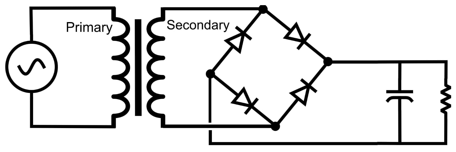
Figure 5. A simple AC/DC Converter
This circuit produces the voltage and current waveforms that appear in Figure 6 (for an explanation of why they look like this, see this article).
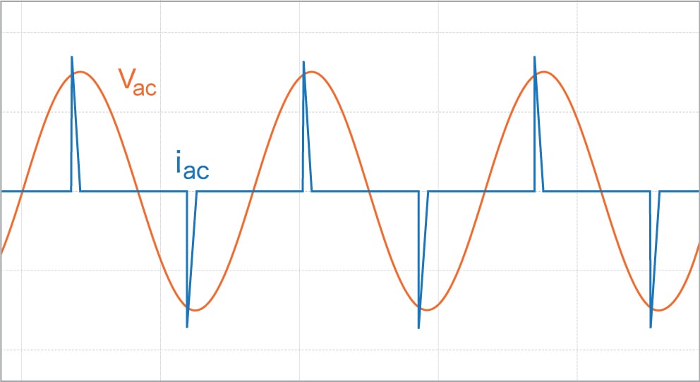
Figure 6. Voltage and current waveforms for a linear power supply
Because of the obvious distortion in the current, you would expect the harmonic current content to be high, and this can be seen in the FFT of the current in Figure 7:
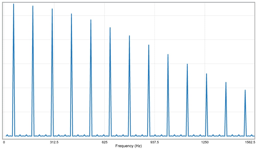
Figure 7. Harmonics of current flowing into a linear power supply
Clearly there is a lot of distortion in the current. Imagine a large scale power system with hundreds or thousands of AC/DC converters connected and the contribution to the harmonic distortion of all of those converters.
Let’s actually quantify the power quality and perform the measurements and calculation for determining the power factor.
To determine the power factor requires two separate measurements. The first is the THD of the current in Figure 6, and it is measured as 2.8 (yes, that means 280%). The second is the phase shift between the fundamental of the current and the voltage and it is about 10 degrees. This means power factor is
$$PowerFactor = cos(10 ^{\circ}) \times \sqrt{\frac{1}{1+(2.8)^2}} = (0.985)(0.336) = 0.331$$
which is a very low power factor indeed, and the biggest contributor to this low power factor is the harmonic distortion of the current.
Example 2: AC/DC Converter with Power Factor Correction
The second example has circuitry as discussed here and shown in Figure 8 that tries to make the current track the voltage as closely as possible. The purpose of this tracking is to improve the power factor, and while this power factor correction is certainly not perfect, it is a big improvement over the first example.
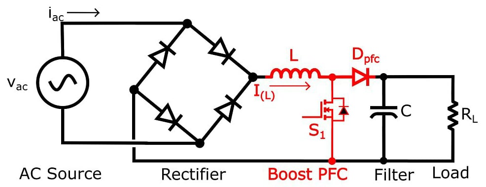
Figure 8. Boost Power Factor Correction Circuit
This circuit produces voltage (vac) and current (iac) waveforms that look like this:
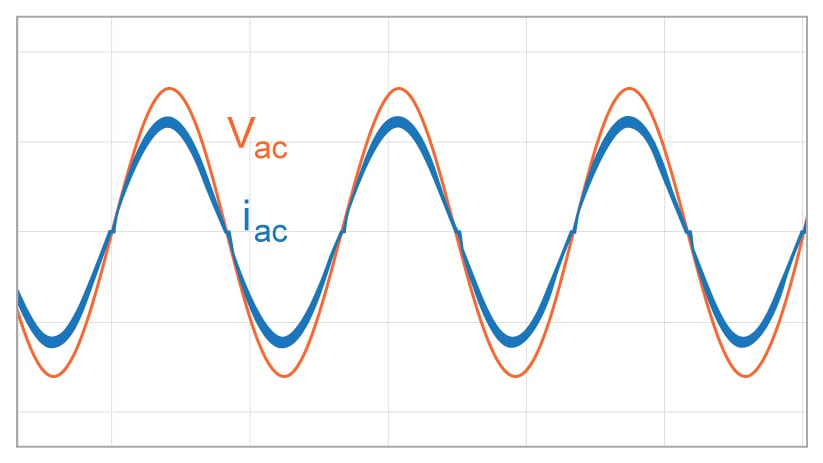
Figure 9. Voltage and current into boost PFC circuit
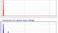
The current is obviously distorted, but not by much; the power factor correction significantly reduces the distortion. This next figure, Figure 10, gives an indication of how much the current harmonics have been reduced when compared to the harmonics in Figure 7.

Figure 10. Harmonics of current into boost PFC circuit
Current harmonics are low and so is the phase difference between voltage and current (about 3º). The combination of the two components, current harmonics (as measured by THD) and phase difference between voltage and current as per equation 5, gives us the power factor. The THD measured in the current signal shown in Figure 9 is 0.2 (or 20%), and the phase shift is 3º, resulting in a power factor of
$$PowerFactor = cos(3^{\circ}) \times \sqrt{\frac{1}{1+(0.2)^2}} = (0.999)(0.98) = 0.979$$
This is a high power factor, but if only displacement factor was (incorrectly) used in this calculation, power factor would have been determined to be 0.999.
Final Words
The full definition of power factor must include the phase relationship between the voltage and current (displacement factor) as well as the harmonic distortion (distortion factor). For simplicity, when the concept of power factor is first introduced, the displacement factor is the part of the power factor that is focused on. For a complete understanding of the power factor and the means to correct it, the distortion factor must also be included in any power factor calculations.
Related Content


Just learned about this in class today - great read!
How about including an index to explain the symbols in the equations so that us dumbys can understand THD in depth as well?