 Facebook
 Google
 GitHub
 Linkedin
Understanding the Photodiode Equivalent Circuit
This article presents a circuit model that helps us to analyze the electrical behavior of a photodiode.
An equivalent circuit helps us to understand and predict the real-life functionality of an electronic component. For photodiodes, an equivalent circuit model is an essential analytical tool, because simply inserting a photodiode symbol into a schematic doesn’t tell you much about the signal that will be generated and the ways in which the photodiode will interact with an amplifier circuit.
This article is the fifth in our series introducing photodiodes. Catch up on the rest to learn about the following:
- pn junctions and how light works
- How light-sensitive pn junctions work
- The modes of photodiodes: photoconductive and photovoltaic
- Semiconductor technologies used in photodiodes
Basic Equivalent Circuit for a Photodiode
Not all photodiode models are exactly the same, but four elements appear consistently: a current source, a parallel capacitor, a parallel resistor, and a series resistor, in addition to a normal pn junction represented by the diode symbol.

Photocurrent
The ideal current source (IPD) represents the photocurrent, i.e., the current generated by the diode in response to incident light. Note that the direction of the photocurrent corresponds to current that flows from the diode’s cathode to the diode’s anode—this is a good reminder that photodiodes are used with zero bias or reverse bias, and the current that they produce flows in the direction opposite to what we expect from normal forward-biased diodes.
As mentioned in the previous article, we use responsivity to quantify the relationship between incident light power and photocurrent. The responsivity of a typical silicon photodiode ranges from about 0.08 amps per watt (A/W) for 400 nm EMR to 0.48 A/W for 700 nm EMR.
Junction Capacitance
The parallel capacitor (CJ) represents the diode’s junction capacitance, i.e., the capacitance associated with the depletion region of the pn junction. Junction capacitance is an important parameter because it strongly influences the photodiode’s frequency response. Lower junction capacitance allows for superior high-frequency operation.
You might notice photodiode models in which CJ is a variable capacitor. Though this representation seems to be less common, it’s not at all a bad idea, because it reminds us that the junction capacitance depends on the bias voltage. We can deliberately design a photodiode system for higher bandwidth by increasing the reverse-bias voltage.

This plot—taken from Photodiode Characteristics and Applications, published by OSI Optoelectronics—conveys the large reductions in junction capacitance that can be achieved by operating a photodiode in photoconductive mode.
Parallel Resistance
The resistor in parallel with the photodiode is called the shunt resistance (RSH). As with current sources in general, ideal operation is achieved when RSH is infinite. With infinite (or, in real life, extremely high) shunt resistance, a current source delivers all of its current to the load, and the current-to-voltage ratio is determined entirely by the load resistance. As the shunt resistance approaches the value of the load resistance, it begins to more noticeably influence the current-to-voltage ratio.
With many photodiodes, shunt resistance is so high that it won’t seriously influence overall performance in typical applications. For silicon photodiodes, RSH is tens, hundreds, or even thousands of megaohms, and indium gallium arsenide can also have extremely high shunt resistance. With germanium, however, you need to be more careful, because RSH will usually be in the kiloohm range, and maybe even the low-kiloohm range.
Shunt resistance also influences noise performance. As RSH decreases, a photodiode’s Johnson noise increases.
Series Resistance
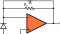
A photodiode has contacts, wire bonds, and semiconductor material that contribute to series resistance (RS). This resistance tends to be quite low, as in several ohms or a few tens of ohms, though higher values are possible.
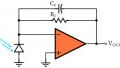
As far as I know, series resistance is usually not a major issue in the design of photodiode systems. However, excessive series resistance can reduce linearity: Photocurrent passing through RS creates a voltage drop that begins to forward bias a photodiode that is operated in a zero-bias configuration (see the diagram below). A forward-biased diode has an exponential current–voltage relationship. Consequently, increasing voltage across RS reduces the photocurrent that reaches the load, because it causes some of the photocurrent to be diverted to ground through the diode itself, and this diversion of current occurs in nonlinear fashion.

Recap
When we’re designing or analyzing a photodiode-based detection circuit, we use an equivalent circuit to help us understand the various electrical parameters involved in photodiode functionality. Essential elements of a photodiode equivalent circuit are a current source for the photocurrent, a diode symbol to represent the pn junction, a capacitor in parallel with the current source, a resistor in parallel with the current source, and a resistor in series with the output current.


Finally!
Someone who explains a photodiode’s operation in an easy to understand form.
Why do we need to model the pn junction itself (with the ideal diode) when it is already being modelled by the junction capacitance, current source and parasitic resistances?