Facebook
 Google
 GitHub
 Linkedin
Writing PICAXE BASIC Code - Part 1
This is the first in a multi-part series on writing PICAXE BASIC code. This article covers how to read PICAXE pin-out diagrams, a circuit for coding practice, and the general program format.
PICAXE microcontrollers are programmed in PICAXE BASIC. By starting simply, explaining programming step by step, and showing program examples, this series of articles will provide you with the fundamental skills required to write code that runs the way you want.
Recommended Level
Beginner
Recommended Prerequisites
Although this is a beginner level project, some knowledge of the PICAXE system would be very beneficial; the reader is advised to understand the baseline information in the following articles:
PICAXE Programming Basics - Part 1
PICAXE Programming Basics - Part 2
PICAXE Pinouts
Hardware design is a precursor to writing software, and in order to design hardware using a PICAXE, it is essential to understand the chip's physical configuration and electrical capabilities. Careful use of correct terminology will help to avoid both hardware and software errors.
PICAXE µCs are available from eight to 40 "legs," which are the metal leads that extend from the bodies of the chips. At least two of the legs are used exclusively for connecting power and ground, but the rest are available for other functions. In the drawing of the PICAXE 08M2+ below, notice that the legs are numbered from 1 through 8, and that legs 1 and 8 are used exclusively for +V and 0V (gnd) respectively.
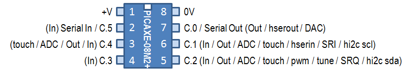
The remaining six legs are designated as "pins" and given individual identifiers consisting of a letter and a number separated by a period: C.0 through C.5, (pronounced "see dot zero" through "see dot five.") These pin numbers are used in PICAXE programs for positive identification by the microcontroller; the "leg" numbers are never used in code (except perhaps in a comment.)
Each PICAXE pin has its own set of capabilities, and these capabilities dictate much of the hardware and software design. For example on the 08M2+, pinC.3 only has one possible use, i.e., as a digital input. On the other hand, pinC.2 can be a digital input, or a digital output, or one of six other things, any of which can be selected by the code. Legs 2 and 7 add another complication. In addition to always serving as the serial in and serial out leads for communication with a PC, they can also be set as pins and, under the right circumstances, perform other functions in code. PinC.5 can be a digital input, and pinC.0 can be a digital output or either of two other functions.
Don't be concerned if you don't know what all those abbreviations stand for, or what the functions are. You will learn them as you need them, and taken one at a time, they are easy to understand and to use.
Coding Test Circuit
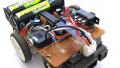
The circuit for testing the code in these articles is shown in the schematic and in the breadboard assembly photograph below. Note that it consists of the PICAXE minimum programming circuit as detailed in PICAXE to PC Communications, plus nine additional components as detailed in the parts list below. The code that is included with this article and additional articles in this series is designed to run on the coding test circuit exactly as shown, and you would be well served to duplicate the assembly as closely as possible.
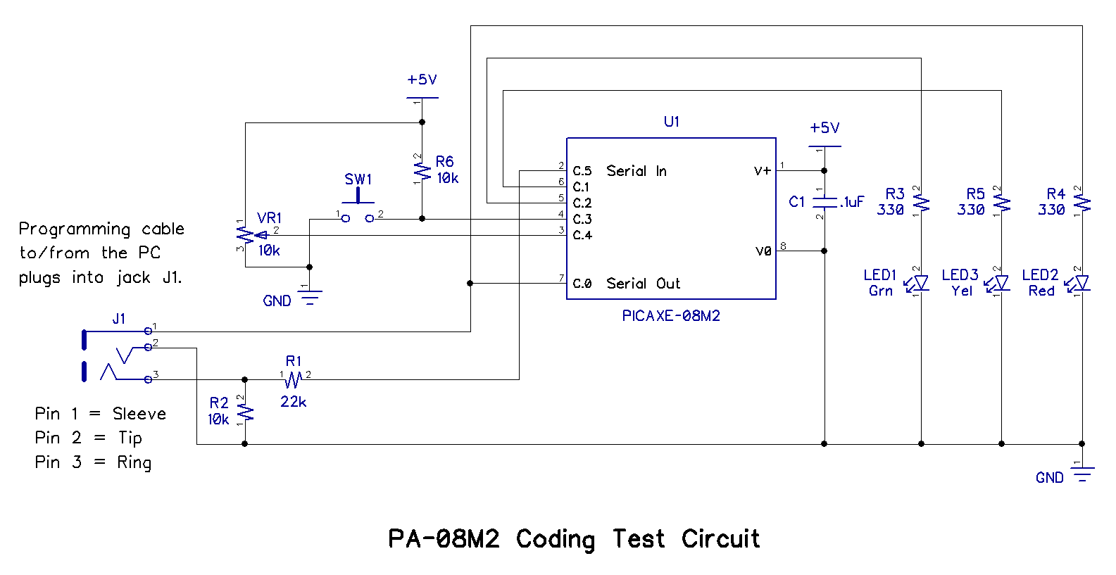
.png)
| PA-08M2 Coding Test Circuit Parts List | ||||
|---|---|---|---|---|
| Designation | Description | Source | Part Number | Comments |
| R1 | Resistor, 1/4W, 22kOhms, (red, red, orange) | Digi-Key | 22KQBK-ND | Required. Okay to substitute similar 1/8 watt or larger part. |
| R2, R6 | Resistor, 1/4W, 10kOhms, (brown, black, orange) | Digi-Key | 10KQBK-ND | Required. Okay to substitute similar 1/8 watt or larger part. |
| R3, R4, R5 | Resistor, 1/4W, 330Ohms, (orange, orange, brown) | Digi-Key | 330QBK-ND | Required. Okay to substitute similar 1/8 watt or larger part. |
| VR1 | Potentiometer, 1/8W, 10kOhms | Digi-Key | 3362P-103LF-ND | Required. Okay to substitute similar 1/8 watt or larger part. |
| SW1 | Switch, Pushbutton, Momentary, Normally Open | Digi-Key | 450-2038-1-ND | Required. Okay to substitute similar part. |
| J1 | Jack, 3.5mm, 3-conductor | Digi-Key | CP1-3533NG-ND | Optional. Depends on programming cable. See article: PICAXE to PC Connections. |
| LED1 | LED, T1, Indicator, Green | Digi-Key | LTL-4231N | Required. Okay to substitute similar part. |
| LED2 | LED, T1, Indicator, Red | Digi-Key | LTL-4221N | Required. Okay to substitute similar part. |
| LED2 | LED, T1, Indicator, Yellow | Digi-Key | LTL-4251N | Required. Okay to substitute similar part. |
| C1 | Capacitor, 50V, .1µF, (104) | Digi-Key | 399-9797-ND | Recommended for noise suppression. Okay to substitute similar part. |
| U1 | Microcontroller, PICAXE 08M2+ | P.H.Anderson.com | PICAXE-08M2+ | Required. Do not substitute. |
| N/A | Cable, PICAXE Programming | TBD | TBD | Cable choice depends on PC ports available. See article: PICAXE to PC Connections. |
| N/A | Breadboard, solderless, 400 contacts | Digi-Key | 377-2094-ND | Required. Okay to substitute similar part. |
| N/A | Wire, jumper, AWG22, solid, tinned, assorted colors | TBD | TBD | Required. Okay to substitute similar part. |
| N/A | Power Supply, 5VDC, 500mA, regulated, filtered | TBD | TBD | Required. Any regulated, filtered, 2.3-5.5VDC, 100mA (min.) power source is okay. |
Assembly of the coding test circuit breadboard is straightforward, partly because it is very similar to the programming test circuit built in Part 1 of PICAXE Programming Basics. However, two new components, a switch and a potentiometer, have been added and a few explanatory comments about them seem worthwhile.
A normally open pushbutton switch (SW1) should be inserted into the solderless breadboard in the location shown. Note that the switch called out in the parts list above has two leads which may need to be trimmed slightly to allow full insertion into holes C23 and C25 of the solderless breadboard. As shown in the photo and the schematic, one side of SW1 is connected through a (black preferred) wire to ground, and the other side is connected through a (green preferred) wire to pinC.3 of the 08M2+. When the pushbutton is depressed, SW1 is closed and pinC.3 is connected to ground, which the 08M2+ recognizes as a logic 0 (zero), also called a logic low. One end of resistor R6, is connected to +5V, and the other end is connected to pinC.3 and, (unless SW1 is closed) holds pinC.3 at +5V. The 08M2+ recognizes +5V as a logic 1, also called a logic high. R6 is a "pull-up" resistor, because it pulls pinC.3 "up" to +5V. Without R6, pinC.3 would be left unconnected, or "floating," while SW1 was open. This floating condition could cause erratic operation of the 08M2+. Thus, R6 was added to avoid ever having pinC.3 unconnected.
In addition, a potentiometer (VR1) has also been added. Note that there are three leads on the bottom of the potentiometer ("pot," for short.) The three leads are identified on the plastic case as 1, 2, and 3. Orient the pot so that lead 1 is over hole B19 in the solderless breadboard, lead 2 is over hole D20, and lead 3 is over hole B21. Insert the three pot leads into the solderless breadboard, and then insert a (black preferred) wire and a (red preferred) wire into the solderless breadboard from the pot to the ground and power rails as shown. Finally, insert a (yellow preferred) wire from hole E20 in the breadboard to hole D16 as shown in the photo above. This connection scheme makes VR1 into a variable output voltage divider, with its output connected to pinC.4 of the 08M2+. Turning the pot control sets the voltage at pinC.4 to any voltage from 0V to +5V .
Opening and Loading the Code File
The latest (and recommended) Integrated Development Environment (IDE) for Windows is PICAXE Editor 6 (PE6;) it will be used in this series of articles. AXEpad is available for Linux and Macintosh users, and provides the essential capabilities of PE6. If you have not already done so, install the IDE of your choice on your computer as described in PICAXE Prgramming Basics - Part 1 (AXEpad,) or Part 2 (PE6.) Start your IDE.
The first program you will need is Flash Red, Yel, Grn.bas and is available for downloading below. Download the code and save it in a convenient location on your computer.
Open Flash Red, Yel, Grn.bas; the program should look like the figure below.

Check the following:
• Your programming cable is connected from the PC to the programming test circuit.
• The correct COM port is selected in the Workplace Explorer Settings pane of PE6.
• PICAXE-08M2 is selected in the Workplace Explorer Settings pane of PE6.
• Power is connected to the coding test circuit breadboard.
Click the Program Download icon in the Home ribbon (or the PICAXE ribbon,) and the downloading should begin. The Workspace Explorer Compiler pane will display the download progress, and conclude with a program successful message. The three LEDs should light for 1/2 second each in red, yellow, green order and repeat as long as power is supplied. If not, there is most likely a wiring error in your coding test circuit breadboard; correct any problems and try again.
A Question or Two and an Explanation
Did you happen to notice that while the program was downloading to the PICAXE that the red LED was flickering? If not, download the code again and watch the red LED.
Do you wonder why the red LED is flickering?
Here's the answer: Look at the schematic and see which pin the red LED is connected to. It's pinC.0, right? And pinC.0 is also the Serial Out lead for the 08M2. During the download, the code is sent from the PC to the PICAXE on the Serial In lead, but the PICAXE sends acknowledgements back on the Serial Out lead, which is also pinC.0. Those acknowledgement signals are what causes the red LED to flicker. That doesn't present a problem with an LED connected to pinC.0, but certain other devices (motors, for example) must be isolated from pinC.0 during program downloading; that will be discussed in more detail in a future article.
Program Analysis
There are thee reasons why Flash Red, Yel, Grn.bas is a very easy program to understand. First of all, it is extremely short, second, it is well commented, and third, the text is automatically color coded by PE6. (Color choices are user selectable, but this article uses the PE6 default color settings.)
All the text in green comprises comments, which are completely unnecessary as far as the µC is concerned. In fact, comments are not even downloaded to the PICAXE, but are there only to help humans reading the code to understand it. As you write code, you should get into the habit of commenting it thoroughly, not only for the sake of others who read your code, but also for your own benefit when (not if) you forget what you were trying to accomplish. Comments are identified to PE6 as being comments by placing an apostrophe or a semi-colon at the beginning. Both the apostrophe and the semi-colon accomplish exactly the same thing; choose one and use it consistently.
Lines 1 through 7 consist of information about the code and the circuit it runs on. This particular set of reminders is just one way of doing it; you should decide what is important for you and design your own code intro, including as much information as you want. Usually, more is better.
Line 8 starts with what is called a "directive," which tells the code which PICAXE chip the code was written for, i.e., an 08M2. Directives always begin with the pound symbol (#) and are always in blue text.
Line 9 contains code; main: is a "label," which identifies a specific place in the code. Labels are in black text.
Line 10 contains code; high C.0 is a "command" to make pinC.0 an output, and set it high. Commands are in light blue text.
Line 11 contains code: low C.2 is a command to set pinC.2 low.
Line 12 contains code; pause 500 is a command to cause the PICAXE to stop any activity for a period of 1/2 second. Pause commands set the time in milliseconds; 500 milliseconds equals 1/2 second.
Lines 13 through 18 continue to make outputs high and low, thus turning the LEDs on and off in a particular sequence. Notice that every line contains an explanatory comment in green text.
Line 19 contains code; goto is a command to cause the µC to go to the place in the code identified by the label following the goto command. In this case, the command sends the PICAXE back to "main" in line 9, and the program continues in the same pattern.
Study the code until you understand it thoroughly; there's lots more to come.
Mission Possible
Flash red, yel, grn.bas contains all the program directives, labels, and commands to control the flash rates and patterns for the three LEDs. Your mission, should you choose to accept it, is to write code to make the LEDs follow the lighting pattern on one side of a traffic light as described below. No hardware changes are required.
• Green flashes on/off 10 times for 10 seconds.
• Green on for 20 seconds, then off.
• Yellow on for 3 seconds, then off.
• Red on for 27 seconds, then off.
• Repeat continuously.
The answer (actually more than one answer) will be in part 2 of this series. Good luck.
Next Article in Series: Writing PICAXE BASIC Code - Part 2