Facebook
 Google
 GitHub
 Linkedin
Introduction to Digital Communication
In the design of large and complex digital systems, it is often necessary to have one device communicate digital information to and from other devices. One advantage of digital information is that it tends to be far more resistant to transmitted and interpreted errors than information symbolized in an analog medium.
This accounts for the clarity of digitally-encoded telephone connections, compact audio disks, and for much of the enthusiasm in the engineering community for digital communications technology. However, digital communication has its own unique pitfalls, and there are multitudes of different and incompatible ways in which it can be sent.
Hopefully, this chapter will enlighten you as to the basics of digital communication, its advantages, disadvantages, and practical considerations.
Suppose we are given the task of remotely monitoring the level of a water storage tank. Our job is to design a system to measure the level of water in the tank and send this information to a distant location so that other people may monitor it.
Measuring the tank’s level is quite easy, and can be accomplished with a number of different types of instruments, such as float switches, pressure transmitters, ultrasonic level detectors, capacitance probes, strain gauges, or radar level detectors.
Example of Analog Communication
For the sake of this illustration, we will use an analog level-measuring device with an output signal of 4-20 mA. 4 mA represents a tank level of 0%, 20 mA represents a tank level of 100%, and anything in between 4 and 20 mA represents a tank level proportionately between 0% and 100%.
If we wanted to, we could simply send this 4-20 milliamp analog current signal to the remote monitoring location by means of a pair of copper wires, where it would drive a panel meter of some sort, the scale of which was calibrated to reflect the depth of water in the tank, in whatever units of measurement preferred.
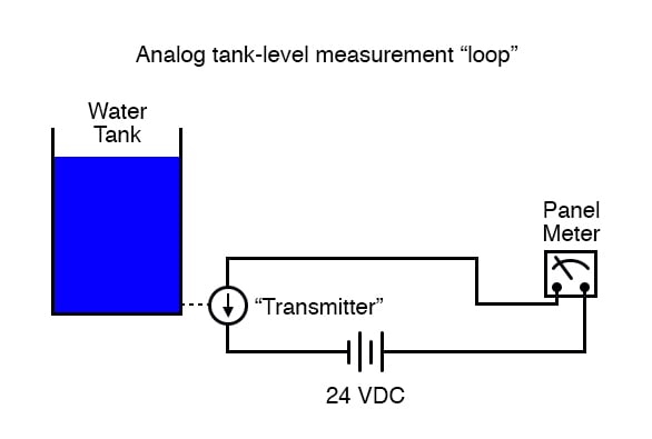
This analog communication system would be simple and robust. For many applications, it would suffice for our needs perfectly. But, it is not the only way to get the job done.
For the purposes of exploring digital techniques, we’ll explore other methods of monitoring this hypothetical tank, even though the analog method just described might be the most practical.
The analog system, as simple as it may be, does have its limitations. One of them is the problem of analog signal interference. Since the tank’s water level is symbolized by the magnitude of DC current in the circuit, any “noise” in this signal will be interpreted as a change in the water level.
With no noise, a plot of the current signal over time for a steady tank level of 50% would look like this:

If the wires of this circuit are arranged too close to wires carrying 60 Hz AC power, for example, inductive and capacitive coupling may create a false “noise” signal to be introduced into this otherwise DC circuit.
Although the low impedance of a 4-20 mA loop (250 Ω, typically) means that small noise voltages are significantly loaded (and thereby attenuated by the inefficiency of the capacitive/inductive coupling formed by the power wires), such noise can be significant enough to cause measurement problems:

The above example is a bit exaggerated, but the concept should be clear: any electrical noise introduced into an analog measurement system will be interpreted as changes in the measured quantity.
One way to combat this problem is to symbolize the tank’s water level by means of a digital signal instead of an analog signal. We can do this really crudely by replacing the analog transmitter device with a set of water level switches mounted at different heights on the tank:

Each of these switches is wired to close a circuit, sending current to individual lamps mounted on a panel at the monitoring location. As each switch closed, its respective lamp would light, and whoever looked at the panel would see a 5-lamp representation of the tank’s level.
Being that each lamp circuit is digital in nature—either 100% on or 100% off—electrical interference from other wires along the run have much less effect on the accuracy of measurement at the monitoring end than in the case of the analog signal.
A huge amount of interference would be required to cause an “off” signal to be interpreted as an “on” signal or vice versa. Relative resistance to electrical interference is an advantage enjoyed by all forms of digital communication over analog.
Now that we know digital signals are far more resistant to error induced by “noise,” let’s improve on this tank level measurement system. For instance, we could increase the resolution of this tank gauging system by adding more switches, for more precise determination of water level.
Suppose we install 16 switches along the tank’s height instead of five. This would significantly improve our measurement resolution but at the expense of greatly increasing the quantity of wires needing to be strung between the tank and the monitoring location.
One way to reduce this wiring expense would be to use a priority encoder to take the 16 switches and generate a binary number which represented the same information:

Now, only 4 wires (plus any ground and power wires necessary) are needed to communicate the information, as opposed to 16 wires (plus any ground and power wires). At the monitoring location, we would need some kind of display device that could accept the 4-bit binary data and generate an easy-to-read display for a person to view.
A decoder, wired to accept the 4-bit data as its input and light 1-of-16 output lamps, could be used for this task, or we could use a 4-bit decoder/driver circuit to drive some kind of numerical digit display.
Still, a resolution of 1/16 tank height may not be good enough for our application. To better resolve the water level, we need more bits in our binary output. We could add still more switches, but this gets impractical rather quickly.
A better option would be to re-attach our original analog transmitter to the tank and electronically convert its 4-20 milliamp analog output into a binary number with far more bits than would be practical using a set of discrete level switches.
Since the electrical noise we’re trying to avoid is encountered along the long run of wire from the tank to the monitoring location, this A/D conversion can take place at the tank (where we have a “clean” 4-20 mA signal). There are a variety of methods to convert an analog signal to digital, but we’ll skip an in-depth discussion of those techniques and concentrate on the digital signal communication itself.
The type of digital information being sent from our tank instrumentation to the monitoring instrumentation is referred to as parallel digital data. That is, each binary bit is being sent along its own dedicated wire, so that all bits arrive at their destination simultaneously.
This obviously necessitates the use of at least one wire per bit to communicate with the monitoring location. We could further reduce our wiring needs by sending the binary data along a single channel (one wire + ground), so that each bit is communicated one at a time. This type of information is referred to as serial digital data.
We could use a multiplexer or a shift register to take the parallel data from the A/D converter (at the tank transmitter), and convert it to serial data. At the receiving end (the monitoring location) we could use a demultiplexer or another shift register to convert the serial data to parallel again for use in the display circuitry.
The exact details of how the mux/demux or shift register pairs are maintained in synchronization is, like A/D conversion, a topic for another lesson. Fortunately, there are digital IC chips called UARTs (Universal Asynchronous Receiver-Transmitters) that handle all these details on their own and make the designer’s life much simpler.
For now, we must continue to focus our attention on the matter at hand: how to communicate the digital information from the tank to the monitoring location.
RELATED WORKSHEETS: