 Facebook
 Google
 GitHub
 Linkedin
Amplifier Impedances
Input impedance varies considerably with the circuit configuration shown in Figure below. It also varies with biasing. Not considered here, the input impedance is complex and varies with frequency. For the common-emitter and common-collector, it is base resistance times β. The base resistance can be both internal and external to the transistor.
For the common-collector:
Rin = βRE
It is a bit more complicated for the common-emitter circuit. We need to know the internal emitter resistance rEE.
This is given by:
rEE = KT/IEm where: K=1.38×10⁻²³ watt-sec/oC, Boltzman's constant T= temperature in Kelvins ≅300. IE = emitter current m = varies from 1 to 2 for Silicon RE ≅ 0.026V/IE = 26mV/IE
Thus, for the common-emitter circuit Rin is
Rin = βrEE
As an example the input resistance of a, β = 100, CE configuration biased at 1 mA is:
rEE = 26mV/1mA = 26 Ω Rin = βrEE = 100(26) = 2600 Ω
Moreover, a more accurate Rin for the common-collector should have included Re’
Rin = β(RE + rEE)
The above equation is also applicable to a common-emitter configuration with an emitter resistor.
Input impedance for the common-base configuration is Rin = rEE.
The high input impedance of the common-collector configuration matches high impedance sources. A crystal or ceramic microphone is one such high impedance source. The common-base arrangement is sometimes used in RF (radio frequency) circuits to match a low impedance source, for example, a 50 Ω coaxial cable feed. For moderate impedance sources, the common-emitter is a good match. An example is a dynamic microphone.
The output impedances of the three basic configurations are listed in the Figure below. The moderate output impedance of the common-emitter configuration helps make it a popular choice for general use. The Low output impedance of the common-collector is put to good use in impedance matching, for example, transformerless matching to a 4 Ohm speaker. There do not appear to be any simple formulas for the output impedances. However, R. Victor Jones develops expressions for output resistance. [RVJ]
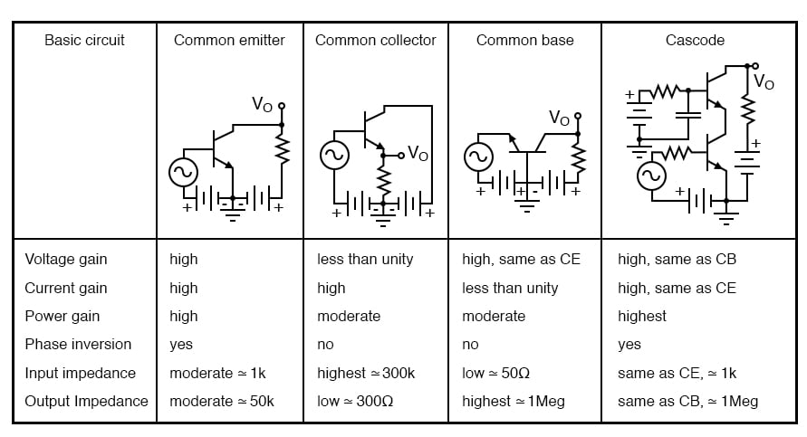
Amplifier characteristics, adapted from GE Transistor Manual, Figure 1.21.
REVIEW:
- See Figure above.
RELATED WORKSHEETS:


Thank you a lot for that figure. Its so hard to find something like that…
Trying to find it again, there is a blatant error somewhere in the article re emitter impedance. 26mV/Ic of 1mA gives 26 ohm, not 0.26 ohm. Otherwise all in order.