Facebook
 Google
 GitHub
 Linkedin
Bridged-Tee Attenuator Calculator
This calculator helps you determine the values of the resistors R1 and R2 to be used for a bridged-tee attenuator.
Output
Overview
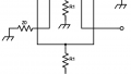
Our bridged-tee attenuator calculator (also called a "bridged-T attenuator") is designed to aid you in calculating the correct values of the resistors R1 and R2, according to the diagram below. The only requirement is the required attenuation in decibels (dB) and the impedance in ohms.

Equations
$$R_{1} = Z_{0}\left [10^{\frac{A_{dB}}{20}}-1 \right ]$$
$$R_{2} = Z_{0}\left [\frac{1}{10^{\frac{A_{dB}}{20}}-1} \right ]$$
Applications
Attenuators, especially those used in RF applications, consist of a network of resistors. These passive circuits are used to weaken or "attenuate" the signal from a source (transmitter) to a level suitable for the destination (receiver). Attenuating a signal is done not only to avoid damage to the receiving-end circuit but also to match the impedance between the source and the destination - a requirement for maximum power transfer.
The bridged-tee attenuator is a modified version of the pi network topology. The advantage of this network over other topologies (particularly the pi and the tee-pad) is the possibility of varying attenuation with only two resistors. Also, it is possible to use the full range of resistor values for both R1 and R2 whereas a pi attenuator resistances can never go below 50 ohms. Another advantage of the bridged-tee topology is its tendency to match impedances even at high attenuation values.
See Also
Reflection Attenuator Calculator
Further Reading
Textbook - Attenuators: Amplifiers and Active Devices