 Facebook
 Google
 GitHub
 Linkedin
Capacitor Charge and Time Constant Calculator
This calculator computes for the capacitor charge time and energy, given the supply voltage and the added series resistance.
Outputs
Calculating Energy Stored in a Capacitor
This calculator is designed to compute for the value of the energy stored in a capacitor given its capacitance value and the voltage across it. The time constant can also be computed if a resistance value is given. Note that the input capacitance must be in microfarads (μF).
Equations
$$E = \frac{CV^{2}}{2}$$
$$\tau = RC$$
Where:
$$V$$ = applied voltage to the capacitor (volts)
$$C$$ = capacitance (farads)
$$R$$ = resistance (ohms)
$$\tau$$ = time constant (seconds)
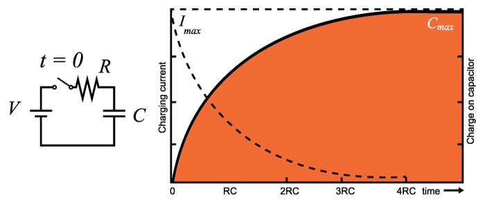
The time constant of a resistor-capacitor series combination is defined as the time it takes for the capacitor to deplete 36.8% (for a discharging circuit) of its charge or the time it takes to reach 63.2% (for a charging circuit) of its maximum charge capacity given that it has no initial charge. The time constant also defines the response of the circuit to a step (or constant) voltage input. Consequently, the cutoff frequency of the circuit is defined by the time constant.
Charging/Discharging Applications
The charging/discharging property of a capacitor made a lot of applications in electrical engineering possible. Here are some of them:
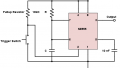
Flash Lamp
The flash lamp of a throwaway camera is powered by the charge stored on a capacitor. The circuit of a flash lamp normally consists of a large high-voltage polarized electrolytic capacitor to store the necessary charge, a flash lamp to generate the required light, a 1.5-v battery, a chopper network to generate a dc voltage in excess of 300 V, and a trigger network to establish a few thousand volts for a very short period of time to fire the flash lamp. It should certainly be of some interest that a single source of energy of only 1.5 V dc can be converted to one of a few thousand volts (albeit for a very short period of time) to fire the flash lamp. In fact, that single, small battery has sufficient power for the entire run of film through the camera.
Surge Protector
In recent years we have all become familiar with the line conditioner as a safety measure for our computers, TVs, CD players, and other sensitive instrumentation. In addition to protecting equipment from unexpected surges in voltage and current, most quality units will also filter out (remove) electromagnetic interference (EMI) and radio-frequency interference (RFI). The filtering is done with the right combination of a resistor and a capacitor. The charging and discharging of the capacitor means it would not allow rapid voltage spikes that would otherwise harm appliances and equipment.
Further Reading
Related Content


It’s important to remember if you use a conventional power source like a battery to charge the capacitor, twice the amount of power (double the Jules stored on the capacitor) will need to be output by the battery. Half of this power will be lost and the other half will remain on the capacitor.
This is often explained by claiming the other half of the power is dissipated in the non ideal circuit elements of the capacitor such as its series resistance, inductance, and radiation losses. However, all these elements create losses before the actual capacitor charges. After factoring in all that loss, the true capacitor must still be presented with double the energy it is going to store. It is an intrinsic property of the capacitor itself that would exist in an ideal circuit element capacitor. Meaning if all non ideal circuit elements were eliminated, the capacitor itself would still “destroy” half the power. This explanation doesn’t fit into the conventional laws that claim energy cannot be destroyed, leading to minimal research on the topic.
The “two capacitor paradox” shares this same problem and solution, claiming non ideal circuit element losses dissipate 50% of the power. However, after an extensive search online, I cannot find any experimental evidence proving this claim, such as experiments measuring the power dissipated by the series resistance of a capacitor based on measuring its temperature, compared to the temperature it should be at for how much power it’s supposedly dissipating. I believe we will eventually come to the conclusion that voltage potential cancellation is a form of energy destruction, while allowing the charge carriers to remain in the system, just not “polarized” as much, retaining the conservation of mass but changing our ideas on the conservation of “energy”.
Additionally, you can eliminate this 50% energy loss by first putting the power into an inductor, then into the capacitor. This fits into the model of voltage affecting energy cancellation. A capacitor and battery start at a constant voltage, and power is lost. An inductor starts at 0v and increases voltage as the capacitor charges. This difference in how the voltage potential is retained explains why one system eliminates half the power while the other retains almost all.