Facebook
 Google
 GitHub
 Linkedin
Network Analysis Techniques
AC Network Analysis
24 questions By Tony R. Kuphaldt
-
Question 13 of 24
Suppose we have two equivalent LR networks, one series and one parallel, such that they have the exact same total impedance (Ztotal):
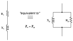
We may write an equation for the impedance of each network in rectangular form, like this:
\(Z_s=R_s+jX_s\) (series network)
\(Z_p= \frac{1}{\frac{1}{R_p}-j \frac{1}{X_p}}\) (parallel network)
Since we are told these two networks are equivalent to one another, with equal impedances, these two expressions in rectangular form must also be equal to each other:
$$R_s+jX_s= \frac{1}{\frac{1}{R_p}-j \frac{1}{X_p}}$$
Algebraically reduce this equation to its simplest form, showing how Rs, Rp, Xs, and Xp relate.
Challenge question: combine the result of that simplification with the equations solving for scalar impedance of series and parallel networks (\(Z^2_s= R^2_s+X^2_s\) for series and \(Z^2_p= \frac{1}{\frac{1}{R^2_p}+\frac{1}{X^2_p}}\) for parallel) to prove the following transformative equations, highly useful for “translating” a series network into a parallel network and visa-versa:
$$Z^2=R_pR_s$$ $$Z^2=X_pX_s$$ Reveal answerDue to the complexity of the algebra, I will show the complete solution here:
$$R_s+jX_s= \frac{1}{\frac{1}{R_p}-j\frac{1}{X_p}}$$
$$(R_s+jX_s) (\frac{1}{R_p}-j \frac{1}{X_p}) = 1$$ $$\frac{R_s}{R_p}-j\frac{R_s}{X_p}+j\frac{X_s}{R_p}-j^2\frac{X_s}{X_p}=1$$
$$\frac{R_s}{R_p}-j\frac{R_s}{X_p}+j\frac{X_s}{R_p}+\frac{X_s}{X_p}=1$$
$$\frac{R_s}{R_p}+\frac{X_s}{X_p}+j(\frac{X_s}{R_p}-\frac{R_s}{X_p})=1$$
Separating real and imaginary terms . . .
\(\frac{R_s}{R_p}+\frac{X_s}{X_p}=1\) = 1 (Real)
\(j (\frac{X_s}{R_p}-\frac{R_s}{X_p}) = j0\) (Imaginary) Just working with the imaginary equation now . . .
$$j (\frac{X_s}{R_p}-\frac{R_s}{X_p}) = j0$$
$$\frac{X_s}{R_p}-\frac{R_s}{X_p}=0$$
$$\frac{X_s}{R_p}=\frac{R_s}{X_p}$$ \(X_pX_s=R_pR_s\) (Solution) In answer to the challenge question, where we now introduce scalar relationships for series and parallel networks:
\(Z^2_s=R^2_s+X^2_s\) Series impedance
\(Z^2_p= \frac{1}{\frac{1}{R^2_p}+\frac{1}{X^2_p}}\) Parallel impedance
Solving each scalar impedance equation for reactance X . . .
$$X^2_s=Z^2_s-R^2_s \ \ \ \ \ \ \ \ \ \ \ \ \ \ \ X^2_p= \frac{1}{\frac{1}{Z^2_p}- \frac{1}{R^2_p}}$$ Preparing the original solution for subsitution . . . $$X_pX_s=R_pR_s$$ $$(X_pX_s)^2=(R_pR_s)^2$$ \(X^2_pX^2_s=R^2_pR^2_s\) Subsituting these definitions for reactance into this prepared equation . . .
$$(\frac{1}{\frac{1}{Z^2_p}-\frac{1}{R^2_p}}) (Z^2_s-R^2_s)=R^2_pR^2_s$$
$$Z^2_s-R^2_s=(R^2_pR^2_s)(\frac{1}{Z^2_p}-\frac{1}{R^2_p})$$
$$Z^2_s-R^2_s= \frac{R^2_pR^2_s}{Z^2_p}-\frac{R^2_pR^2_s}{R^2_p}$$
$$Z^2_s-R^2_s= \frac{R^2_pR^2_s}{Z^2_p}-R^2_s$$
$$Z^2_s= \frac{R^2_pR^2_s}{Z^2_p}$$
$$Z^2_pZ^2_s=R^2_pR^2_s$$
$$(Z_pZ_s)^2=(R_pR_s)^2$$
$$\sqrt{(Z_pZ_s)^2}=\sqrt{(R_pR_s)^2}$$
$$Z_pZ_s=R_pR_s$$
Since the two networks are known to be equivalent, Zp = Zs , which I will now simply label as Z . . . $$ZZ=R_pR_s$$ \(Z^2=R_pR_s\) (Solution) And since we know that Rp Rs = Xp Xs as well . . . \(Z^2=X_pX_s\) (Solution) Follow-up question: the original equivalent networks were comprised of a resistor (R) and an inductor (L). Show that these solutions (Z2 = Rp Rs and Z2 = Xp Xs) hold true for resistor-capacitor series and parallel equivalent networks as well.
Notes:Yes, it is out of character for me to show two pages of solution in the “answer” section of one of my questions! I usually do not provide this much information in my answers. However, in this case I believe there is still much to be learned from examining a proof like this shown step-by-step.
You may wish to ask your students to explain the rationale behind each step, especially in the first part where we deal with real and imaginary terms. One point that may be especially confusing is where I separate the real and imaginary terms, setting the imaginary quantity equal to j0. Some students may not see where the j0 comes from, since the preceding (complex) expression was simply equal to 1. Remind them that “1” is a real quantity, possessing an (implied) imaginary component of 0, and that it could very well have been written as 1 j0.
-
Question 14 of 24
Determine the phase shift of the output voltage (Vout) with reference to the source voltage (0o) for each of the two switch positions, assuming the source frequency is such that XC = R:

Note: you should be able to do all the necessary math mentally, without the aid of a calculating device!
Reveal answerSwitch left: Θ = -45o (Vout lagging behind the source voltage)
Switch right: Θ = 45o (Vout leading ahead of the source voltage)
Follow-up question: identify the effects of various component failures in this circuit.
Notes:This is a very interesting circuit to built and test. You may build one using 1 μF capacitors and 2.7 kΩ resistors that will successfully operate on 60 Hz power-line excitation.
-
Question 15 of 24
This interesting bridge circuit is a variable phase-shifter. It works best when the excitation frequency is such that XC = R in each arm of the bridge:
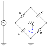
Supposing that XC does equal R in each arm of the bridge, and that the potentiometer resistance is sufficiently high to limit current through it to a negligible level (in other words, Rpot >> R). Calculate the phase shift of Vout with respect to the excitation source voltage when:
- The potentiometer wiper is fully left:
- The potentiometer wiper is fully right:
- The potentiometer wiper is perfectly centered:
Reveal answer- The potentiometer wiper is fully left: Θ = −45o
- The potentiometer wiper is fully right: Θ = 45o
- The potentiometer wiper is perfectly centered: Θ = 0o
Follow-up question: this circuit works best with the excitation frequency is such that XC = R. Write a formula that solves for the necessary frequency (f) to achieve this condition given a certain value of R.
Notes:This is a very interesting circuit to built and test. You may build one using 1 μF capacitors, 2.7 kΩ resistors, and a 100 kΩ potentiometer that will successfully operate on 60 Hz power-line excitation.
An interesting thing to note about using line power is that any distortions in the excitation sine-wave will become obvious when the potentiometer wiper is turned toward the differentiating position (where Θ is positive). If listened to with an audio detector, you may even hear the change in timbre while moving the wiper from one extreme to the other. If excited by a “clean” sine-wave, however, no change in timbre should be heard because there are no harmonics present.