
 Facebook
 Google
 GitHub
 Linkedin
DC Electric Circuits
Ammeter Design
13 questions By Tony R. Kuphaldt
-
Question 1 of 13
What would happen to this meter movement, if connected directly to a 6-volt battery?
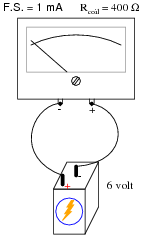
Reveal answerTwo things would happen: first, the movement would most likely be damaged from excessive current. Secondly, the needle would move to the left instead of the right (as it normally should), because the polarity is backward.
Notes:When an electromechanical meter movement is overpowered, causing the needle to “slam” all the way to one extreme end of motion, it is commonly referred to as “pegging” the meter. I’ve seen meter movements that have been “pegged” so badly that the needles are bent from hitting the stop!
Based on your students knowledge of meter movement design, ask them to tell you what they think might become damaged in a severe over-power incident such as this. Tell them to be specific in their answers.
-
Question 2 of 13
We know that connecting a sensitive meter movement directly in series with a high-current circuit is a Bad Thing. So, I want you to determine what other component(s) must be connected to the meter movement to limit the current through its coil, so that connecting the circuit in series with a 1-amp circuit results in the meter’s needle moving exactly to the full-scale position.
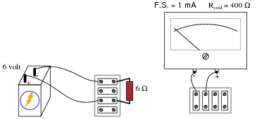
In your diagram, show both the extra component(s) and the manner in which the meter assembly will be connected to the battery/resistor circuit to measure current.
Reveal answer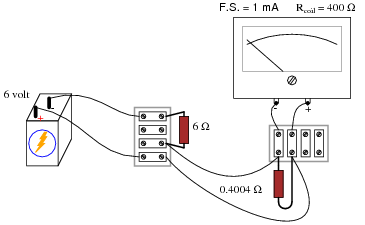
Follow-up question: given the 0 to 1 amp range of the ammeter created by the 0.4004 Ω “shunt” resistor, how much current will the meter actually register when connected in series with the 6 volt battery and 6 ohm resistor? Is this the real current, or is the meter giving us a false indication?
Notes:Beginning students sometimes feel “lost” when trying to answer a question like this. They may know how to apply Ohm’s Law to a circuit, but they do not know how to design a circuit that makes use of Ohm’s Law for a specific purpose. If this is the case, you may direct their understanding through a series of questions such as this:
- Why does the meter movement “peg” if directly connected to the battery?
- What type of electrical component could be used to direct current “away” from the movement, without limiting the measured current?
- How might we connect this component to the meter (series or parallel)? (Draw both configurations and let the student determine for themselves which connection pattern fulfills the goal of limiting current to the meter.)
The follow-up question is quite interesting, and causes students to carefully evaluate the performance of the ammeter they’ve “created”. At root, the problem is similar to that of voltmeter loading, except of course that we’re dealing with ammeters here rather than voltmeters.
-
Question 3 of 13
Determine the measurement range of this ammeter:
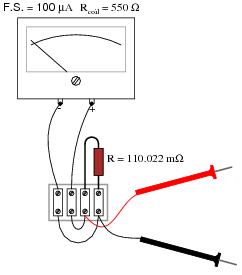
Reveal answerRange = 500 mA
Notes:Determining the ranges for this ammeter is simply an exercise in Ohm’s Law. It is very important that your students recognize the shunt resistor’s value as being in milliohms and not Megaohms! Yes, there is a difference between a lower-case letter “m” and a capital letter “M”!






Hi, Another solution for question 2 could be a parallel connection of the Anmeter with a serial resistor of 6000-400= 5600ohms in parallel with the 6 ohms resistor. Is that correct ?
have answr to immediate follow questions…...........prevent scrolloing.