
 Facebook
 Google
 GitHub
 Linkedin
Discrete Semiconductor Devices and Circuits
Basic AC-DC Power Supplies
31 questions By Tony R. Kuphaldt
-
Question 19 of 31
A technician is troubleshooting a power supply circuit with no DC output voltage. The output voltage is supposed to be 15 volts DC:
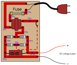
The technician begins making voltage measurements between some of the test points (TP) on the circuit board. What follows is a sequential record of his measurements:
- VTP9−TP10 = 0 volts DC
- VTP1−TP2 = 117 volts AC
- VTP1−TP3 = 117 volts AC
- VTP5−TP6 = 0 volts AC
- VTP7−TP8 = 0.1 volts DC
- VTP5−TP4 = 12 volts AC
- VTP7−TP6 = 0 volts DC
Based on these measurements, what do you suspect has failed in this supply circuit? Explain your answer. Also, critique this technician’s troubleshooting technique and make your own suggestions for a more efficient pattern of steps.
Reveal answerThere is an “open” fault between TP4 and TP6.
Follow-up question: with regard to the troubleshooting technique, this technician seems to have started from one end of the circuit and moved incrementally toward the other, checking voltage at almost every point in between. Can you think of a more efficient strategy than to start at one end and work slowly toward the other?
Notes:Troubleshooting scenarios are always good for stimulating class discussion. Be sure to spend plenty of time in class with your students developing efficient and logical diagnostic procedures, as this will assist them greatly in their careers.
-
Question 20 of 31
AC-DC power supplies are a cause of harmonic currents in AC power systems, especially large AC-DC power supplies used in motor control circuits and other high-power controls. In this example, I show the waveforms for output voltage and input current for an unloaded AC-DC power supply with a step-down transformer, full-wave rectifier, and capacitive filter circuit (the unfiltered DC voltage waveform is shown as a dashed line for reference):
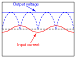
As you can see, the input current waveform lags the voltage waveform by 90o, because when the power supply is unloaded, the only input current is the magnetizing current of the transformer’s primary winding.
With increased loading, the output ripple voltage becomes more pronounced. This also changes the input current waveform significantly, making it non-sinusoidal. Trace the shape of the input current waveform, given the output voltage waveform and magnetizing current waveform (dotted line) shown here:
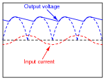
The non-filtered DC output waveform is still shown as a dotted line, for reference purposes.
Reveal answer
Challenge question: does the input current waveform shown here contain even-numbered harmonics (i.e. 120 Hz, 240 Hz, 360 Hz)?
Notes:In a filtered DC power supply, the only time current is drawn from the rectifier is when the filter capacitor charges. Thus, the only time you see input current above and beyond the magnetizing current waveform is when the capacitor voltage requires charging.
Note that although the (sinusoidal) magnetizing current waveform is 90o out of phase with the voltage waveform, the input current transients are precisely in-phase with the current transients on the transformer’s secondary winding. This reviews an important principle of transformers: that whatever primary current is the result of secondary winding load is in-phase with that secondary load current. In this regard, a transformer does not act as a reactive device, but a direct power-coupling device.
Note also that after the initial surge (rising pulse edge) of current, the input current waveform follows a different curve from the voltage waveform, because i = C[dv/dt] for a capacitor.
In case you haven’t guessed by now, there is a lot of stuff happening in this circuit! I would consider this question to be ädvanced” for most introductory-level courses, and may be skipped at your discretion.
-
Question 21 of 31
Power supplies are sometimes equipped with EMI/RFI filters on their inputs, to prevent high-frequency “noise” voltage created within the power supply circuit from getting back to the power source where it might interfere with other powered equipment. This is especially useful for “switching” power supply circuits, where transistors are used to switch power on and off very rapidly in the voltage transformation and regulation process:

Determine what type of filter circuit this is (LP, HP, BP, or BS), and also determine the inductive and capacitive reactances of its components at 60 Hz, if the inductors are 100 μH each and the capacitors are 0.022 μF each.
Reveal answerXL = 0.0377 Ω (each)
XC = 120.6 kΩ (each)
Notes:Ask your students how they determined the identity of this filter. Are they strictly memorizing filter configurations, or do they have a technique for determining what type of filter circuit it is based on basic electrical principles (reactance of components to different frequencies)? Remind them that rote memorization is a very poor form of learning!







i m using power supply for CCTV PTZ Camera with his adaptor rating of 230v AC input & 24V AC Output ,2A load current. what would be the power consumption is their from the main supply line? means is it taking 2 amp from main line of it would be from the adaptor itself?