
 Facebook
 Google
 GitHub
 Linkedin
Discrete Semiconductor Devices and Circuits
Basic AC-DC Power Supplies
31 questions By Tony R. Kuphaldt
-
Question 16 of 31
Identify the voltages that are supposed to appear between the listed test points:
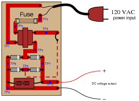
- VTP1−TP2 =
- VTP1−TP3 =
- VTP2−TP3 =
- VTP4−TP5 =
- VTP5−TP6 =
- VTP7−TP8 =
- VTP9−TP10 =
Assume that the power transformer has a step-down ratio of 9.5:1.
Reveal answer- VTP1−TP2 = 120 volts AC
- VTP1−TP3 = 120 volts AC
- VTP2−TP3 = 0 volts
- VTP4−TP5 = 12.63 volts AC
- VTP5−TP6 = 12.63 volts AC
- VTP7−TP8 = 16.47 volts DC
- VTP9−TP10 = 16.47 volts DC
Notes:Before one can troubleshoot a malfunctioning circuit, one must know what voltages and currents are supposed to be in various portions of the circuit. This question, therefore, is a prelude to further troubleshooting questions.
-
Question 17 of 31
A technician is troubleshooting a power supply circuit with no DC output voltage. The output voltage is supposed to be 15 volts DC:
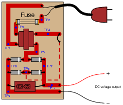
The technician begins making voltage measurements between some of the test points (TP) on the circuit board. What follows is a sequential record of his measurements:
- VTP9−TP10 = 0 volts DC
- VTP8−TP7 = 0 volts DC
- VTP8−TP5 = 0 volts DC
- VTP6−TP7 = 0 volts DC
- VTP4−TP5 = 0 volts AC
- VTP1−TP3 = 0 volts AC
- VTP1−TP2 = 116 volts AC
Based on these measurements, what do you suspect has failed in this supply circuit? Explain your answer. Also, critique this technician’s troubleshooting technique and make your own suggestions for a more efficient pattern of steps.
Reveal answerThe fuse is blown open.
Follow-up question: with regard to the troubleshooting technique, this technician seems to have started from one end of the circuit and moved incrementally toward the other, checking voltage at almost every point in between. Can you think of a more efficient strategy than to start at one end and work slowly toward the other?
Notes:Troubleshooting scenarios are always good for stimulating class discussion. Be sure to spend plenty of time in class with your students developing efficient and logical diagnostic procedures, as this will assist them greatly in their careers.
-
Question 18 of 31
A technician is troubleshooting a power supply circuit with no DC output voltage. The output voltage is supposed to be 15 volts DC:
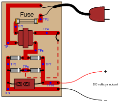
The technician begins making voltage measurements between some of the test points (TP) on the circuit board. What follows is a sequential record of her measurements:
- VTP1−TP2 = 118 volts AC
- VTP3−TP2 = 0 volts AC
- VTP1−TP3 = 118 volts AC
- VTP4−TP5 = 0.5 volts AC
- VTP7−TP8 = 1.1 volts DC
- VTP9−TP10 = 1.1 volts DC
Based on these measurements, what do you suspect has failed in this supply circuit? Explain your answer. Also, critique this technician’s troubleshooting technique and make your own suggestions for a more efficient pattern of steps.
Reveal answerThe transformer has an open winding.
Follow-up question #1: with regard to the troubleshooting technique, this technician seems to have started from one end of the circuit and moved incrementally toward the other, checking voltage at almost every point in between. Can you think of a more efficient strategy than to start at one end and work slowly toward the other?
Challenge question: based on the voltage measurements taken, which do you think is the more likely failure, an open primary winding or an open secondary winding?
Follow-up question #2: how could you test the two windings of the transformer for a possible open fault? In other words, is there another type of measurement that could verify our hypothesis of a failed winding?
Notes:Troubleshooting scenarios are always good for stimulating class discussion. Be sure to spend plenty of time in class with your students developing efficient and logical diagnostic procedures, as this will assist them greatly in their careers.
Students may be puzzled by the presence of DC voltage between TP7 and TP8, and also between TP9 and TP10 (1.1 volts), given that there is less than that amount of AC voltage at the rectifier’s input. However, this is a common phenomenon with electrolytic capacitors, to “recover” a small voltage after having been discharged.





i m using power supply for CCTV PTZ Camera with his adaptor rating of 230v AC input & 24V AC Output ,2A load current. what would be the power consumption is their from the main supply line? means is it taking 2 amp from main line of it would be from the adaptor itself?