
 Facebook
 Google
 GitHub
 Linkedin
Discrete Semiconductor Devices and Circuits
Basic AC-DC Power Supplies
31 questions By Tony R. Kuphaldt
-
Question 13 of 31
What will be the consequence of one diode failing open in the bridge rectifier of a single-phase power supply?
Reveal answerThe (unfiltered) output voltage will be half-wave, not full-wave.
Notes:A question such as this is best discussed while viewing the schematic diagram for a bridge rectifier. I recommend projecting an image of a bridge rectifier circuit on a whiteboard, then having students use dry-erase markers to “mark up” the schematic with arrows for current, voltage drop indications, etc. This way, mistakes can be corrected, or alternate cycles erased and re-drawn, without having to erase and re-draw the schematic diagram itself.
-
Question 14 of 31
Suppose you suspected a failed-open diode in this power supply circuit. Describe how you could detect its presence without using an oscilloscope:
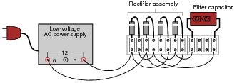
Incidentally, the “low voltage AC power supply” is nothing more than a step-down transformer with a center-tapped secondary winding.
Reveal answer“Remove all diodes from the circuit and test them individually” is not an acceptable answer to this question. Think of a way that they could be checked while in-circuit (ideally, without having to shut off power to the circuit).
Notes:A common tendency for students is to troubleshoot using the “shotgun approach,” which is to remove each component one-by-one and test it. This is a very time-intensive and inefficient method of troubleshooting. Instead, students need to develop diagnostic procedures not requiring removal of components from the circuit. At the very least, there should be some way we can narrow the range of possibilities using in-circuit tests prior to removing components.
-
Question 15 of 31
A student learns that a rectifier circuit is often followed by a low-pass filter circuit in an AC-DC power supply to reduce “ripple” voltage on the output. Looking over his notes from AC theory, the student proceeds to build this power supply circuit complete with a low-pass filter at the output:

While this design will work, there are better filter configurations for this application. Describe the limitations of the circuit shown, and explain how some of the other filters would do a better job.
Reveal answerThe resistor R tends to limit the output current, resulting in less-than-optimal voltage regulation (the output voltage “sagging” under load). Better filter configurations include all forms of LC ripple filters, including the popular “pi” (π) filter.
Follow-up question: in some applications - especially where very large filter capacitors are used - it is a good idea to place a series resistor before the capacitor. Such a resistor is typically rated at a low value so as to not cause excessive output voltage “sag” under load, but its resistance does serve a practical purpose. Explain what this purpose might be.
Notes:Challenge your students with this question: is this the right kind of filter circuit (low pass, high pass, band pass, band stop) to be using, anyway? This question presents a good opportunity to review basic filter theory.
The follow-up question asks students to think carefully about the possible positive benefits of having a series resistor before the capacitor as shown in the student’s original design. If your students are experiencing difficulty understanding why a resistor would ever be necessary, jog their memories with this formula:
i = C dv dt



i m using power supply for CCTV PTZ Camera with his adaptor rating of 230v AC input & 24V AC Output ,2A load current. what would be the power consumption is their from the main supply line? means is it taking 2 amp from main line of it would be from the adaptor itself?