Facebook
 Google
 GitHub
 Linkedin
Discrete Semiconductor Devices and Circuits
Conventional Transistor Overview and Special Transistors
13 questions By Tony R. Kuphaldt
-
Question 1 of 13
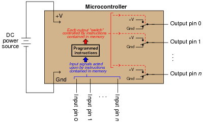
A microcontroller is a specialized type of digital computer used to provide automatic sequencing or control of a system. Microcontrollers differ from ordinary digital computers in being very small (typically a single integrated circuit chip), with several dedicated pins for input and/or output of digital signals, and limited memory. Instructions programmed into the microcontroller’s memory tell it how to react to input conditions, and what types of signals to send to the outputs.
The simplest type of signal “understood” by a microcontroller is a discrete voltage level: either “high” (approximately V) or “low” (approximately ground potential) measured at a specified pin on the chip. Transistors internal to the microcontroller produce these “high” and “low” signals at the output pins, their actions being modeled by SPDT switches for simplicity’s sake:
It does not require much imagination to visualize how microcontrollers may be used in practical systems: turning external devices on and off according to input pin and/or time conditions. Examples include appliance control (oven timers, temperature controllers), automotive engine control (fuel injectors, ignition timing, self-diagnostic systems), and robotics (servo actuation, sensory processing, navigation logic). In fact, if you live in an industrialized nation, you probably own several dozen microcontrollers (embedded in various devices) and don’t even realize it!
One of the practical limitations of microcontrollers, though, is their low output drive current limit: typically less than 50 mA. The miniaturization of the microcontroller’s internal circuitry prohibits the inclusion of output transistors having any significant power rating, and so we must connect transistors to the output pins in order to drive any significant load(s).
Suppose we wished to have a microcontroller drive a DC-actuated solenoid valve requiring 2 amps of current at 24 volts. A simple solution would be to use an NPN transistor as an “interposing” device between the microcontroller and the solenoid valve like this:
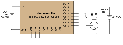
Unfortunately, a single BJT does not provide enough current gain to actuate the solenoid. With 20 mA of output current from the microcontroller pin and a β of only 25 (typical for a power transistor), this only provides about 500 mA to the solenoid coil.
A solution to this problem involves two bipolar transistors in a Darlington pair arrangement:

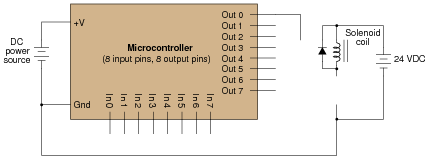
However, there is another solution yet - replace the single BJT with a single MOSFET, which requires no drive current at all. Show how this may be done:
Reveal answer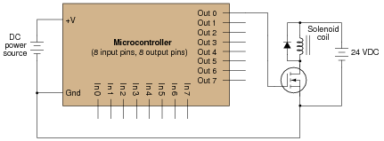
Notes:The purpose of this long-winded question is not just to have students figure out how to replace a BJT with a MOSFET, but also to introduce them to the concept of the microcontroller, which is a device of increasing importance in modern electronic systems.
Some students may inquire as to the purpose of the diode in this circuit. Explain to them that this is a commutating diode, sometimes called a free-wheeling diode, necessary to prevent the transistor from being overstressed by high-voltage transients produced by the solenoid coil when de-energized (“inductive kickback”).
-
Question 2 of 13
Examine the following transistor symbol:

Identify the following:
- Type of transistor (BJT, JFET, or MOSFET)
- Semiconductor doping (NPN, PNP ; N-channel, P-channel)
- Identification of all 3 terminals (Base, Collector, Emitter ; Gate, Drain, Source)
- Direction of each terminal’s current for proper transistor operation (be sure to note whether you are using conventional flow or electron flow notation. If current direction is unimportant, or if there is no current at all, be sure to say so!)
Reveal answer
Notes:This question probes some basic yet important knowledge about transistor identify and operation. If students have difficulty identifying all the parameters asked for in this question, you need to spend more time on transistor fundamentals before proceeding with any other aspects of transistor circuitry!
-
Question 3 of 13
Examine the following transistor symbol:

Identify the following:
- Type of transistor (BJT, JFET, or MOSFET)
- Semiconductor doping (NPN, PNP ; N-channel, P-channel)
- Identification of all 3 terminals (Base, Collector, Emitter ; Gate, Drain, Source)
- Direction of each terminal’s current for proper transistor operation (be sure to note whether you are using conventional flow or electron flow notation. If current direction is unimportant, or if there is no current at all, be sure to say so!)
Reveal answer
Notes:This question probes some basic yet important knowledge about transistor identify and operation. If students have difficulty identifying all the parameters asked for in this question, you need to spend more time on transistor fundamentals before proceeding with any other aspects of transistor circuitry!