
 Facebook
 Google
 GitHub
 Linkedin
Digital Circuits
Flip-Flop Circuits
26 questions By Tony R. Kuphaldt
-
Question 4 of 26
Determine the final output states over time for the following circuit, built from D-type gated latches:
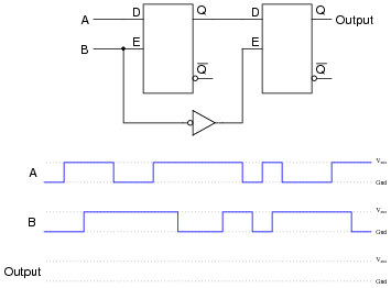
At what specific times in the pulse diagram does the final output assume the input’s state? How does this behavior differ from the normal response of a D-type latch?
Reveal answer
The final output assumes the same logic state as the input only when the enable input signal (B) transitions from “high” to “low”.
Notes:Note that by adding another latch, the overall behavior only slightly resembles the behavior of a D-type latch. With the addition of the second latch, we’ve changed this circuit into a flip-flop, specifically of the master-slave variety.
-
Question 5 of 26
Usually, propagation delay is considered an undesirable characteristic of logic gates, which we simply have to live with. Other times, it is a useful, even necessary, trait. Take for example this circuit:

If the gates constituting this circuit had zero propagation delay, it would perform no useful function at all. To verify this sad fact, analyze its steady-state response to a “low” input signal, then to a “high” input signal. What state is the AND gate’s output always in?
Now, consider propagation delay in your analysis by completing a timing diagram for each gate’s output, as the input signal transitions from low to high, then from high to low:
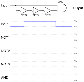
What do you notice about the state of the AND gate’s output now?
Reveal answer
Follow-up question: describe exactly what conditions are necessary to obtain a “high” signal from the output of this circuit, and what determines the duration of this “high” pulse.
Notes:Tell your students that this circuit is a special type of one-shot, outputting a single pulse of limited duration for each leading-edge transition of the input signal.
Ask your students what we might do if we wanted to make the output pulse of this one-shot circuit longer (or shorter).
-
Question 6 of 26
Explain how you would use an oscilloscope to measure the propagation delay of a semiconductor logic gate. Draw a schematic diagram, if necessary. Are the propagation delay times typically equal for a digital gate transitioning from “low” to “high”, versus from “high” to “low”? Consult datasheets to substantiate your answer.
Also, comment on whether or not electromechanical relays have an equivalent parameter to propagation delay. If so, how do you suppose the magnitude of a relay’s delay compares to that of a semiconductor gate, and why?
Reveal answerI’ll leave the experimental design details up to you. However, I will tell you that you do not necessarily have to use a digital storage oscilloscope to “capture” a transient waveform to measure propagation delay, if you apply a little creativity. Hint: use a signal generator to send a high-frequency square wave to the gate of your choice, and use a non-storage oscilloscope to monitor the results.
And yes, electromechanical relays also have intrinsic delay times, which tend to be far greater than those encountered with semiconductor logic gates.
Notes:This question makes an excellent in-class demonstration. It shows this practical parameter in terms the students should be able to kinesthetically relate to.
Hold your students accountable for researching datasheets, rather than just looking up the information in a textbook. Ultimately, reading datasheets and applications notes written by the manufacturers will keep them abreast of the latest technology much more effectively than textbooks, since most textbooks I’ve seen tend to lag behind state-of-the-art by a few years at the least. There is wealth of information to be gained from manufacturers’ literature, so prepare your students to use it!
Explain to your students that relays not only have actuation delay, but most of them also exhibit significant contact bounce as well. Contact bounce is a problem especially where relays send signals to solid-state logic circuitry, to a much greater extent than where relays send signals to other relays. Special-purpose relays can be obtained whose designs minimize actuation time and bounce, but both characteristics are far worse than any equivalent effects in semiconductor logic gates.


