Facebook
 Google
 GitHub
 Linkedin
Digital Circuits
Flip-Flop Circuits
26 questions By Tony R. Kuphaldt
-
Question 7 of 26
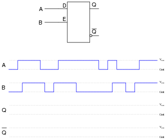
Determine the Q and [Q] output states of this D-type gated latch, given the following input conditions:
Now, suppose we add a propagation-delay-based one-shot circuit to the Enable line of this D-type gated latch. Re-analyze the output of the circuit, given the same input conditions:
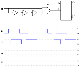
Comment on the differences between these two circuits’ responses, especially with reference to the enabling input signal (B).
Reveal answer

Follow-up question: one of these circuits is referred to as edge-triggered. Which one is it?
Challenge question: in reality, the output waveforms for both these scenarios will be shifted slightly due to propagation delays within the constituent gates. Re-draw the true outputs, accounting for these delays.
Notes:Discuss with your students the concept of edge-triggering, and how it is implemented in (one of) the circuits in this question. Ask them to describe any tips they may have discovered for analyzing pulse waveforms. Specifically, are there any particular times where we need to pay close attention to the D input signal to determine what the outputs do, and any times where we can ignore the D input status?
The challenge question regarding propagation delays is meant to remind students that the perfectly synchronized timing diagrams seen in textbooks are not exactly what happens in real life. Ask your students to elaborate on what real-life conditions would make such propagation delays relevant. Are there applications of digital circuits where we can all but ignore such delays?
-
Question 8 of 26
Shown here are two digital components: a D-type latch and a D-type flip-flop:

Other than the silly name, what distinguishes a “flip-flop” from a latch? How do the two circuits differ in function?
Reveal answerA “flip-flop” is a latch that changes output only at the rising or falling edge of the clock pulse.
Notes:Note to your students that the timing input of a flip-flop is called a clock rather than an enable. Ask them to identify what differences in symbolism show this distinction between the two devices.
-
Question 9 of 26
Explain how the addition of a propagation-delay-based one-shot circuit to the enable input of an S-R latch changes its behavior:

Specifically, reference your answer to a truth table for this circuit.
Reveal answerThe outputs of this device are allowed to change state only when the “clock” signal (C) is transitioning from low to high:

Challenge question: what exactly happens in the “invalid” state for this S-R flip-flop?
Notes:Discuss with your students what happens in this circuit when the clock signal is doing anything other than transitioning from low to high. What condition(s) are equivalent in a regular S-R gated latch circuit?
The challenge question is especially tricky to answer. “invalid” states are easy to determine in regular S-R latch circuits, gated or un-gated. However, because an S-R flip-flop is only momentarily “gated” by the edge of the clock signal, the states its outputs fall to after that edge event has passed is much more difficult to determine.